
Methods and apparatus for suspending vehicles

a technology for suspension devices and vehicles, applied in the direction of shock absorbers, cycles, transportation and packaging, etc., can solve the problems of ineffectiveness of many vehicle types, arbitrary opening and closing without functional benefits, and limited design of air-type springs, illustrated in the '364 patent, to avoid more sophisticated mechanisms that include fluidly isolated dampers

Active Publication Date: 2014-11-25
FOX FACTORY
View PDF6 Cites 28 Cited by
  • Summary
  • Abstract
  • Description
  • Claims
  • Application Information

AI Technical Summary

Benefits of technology

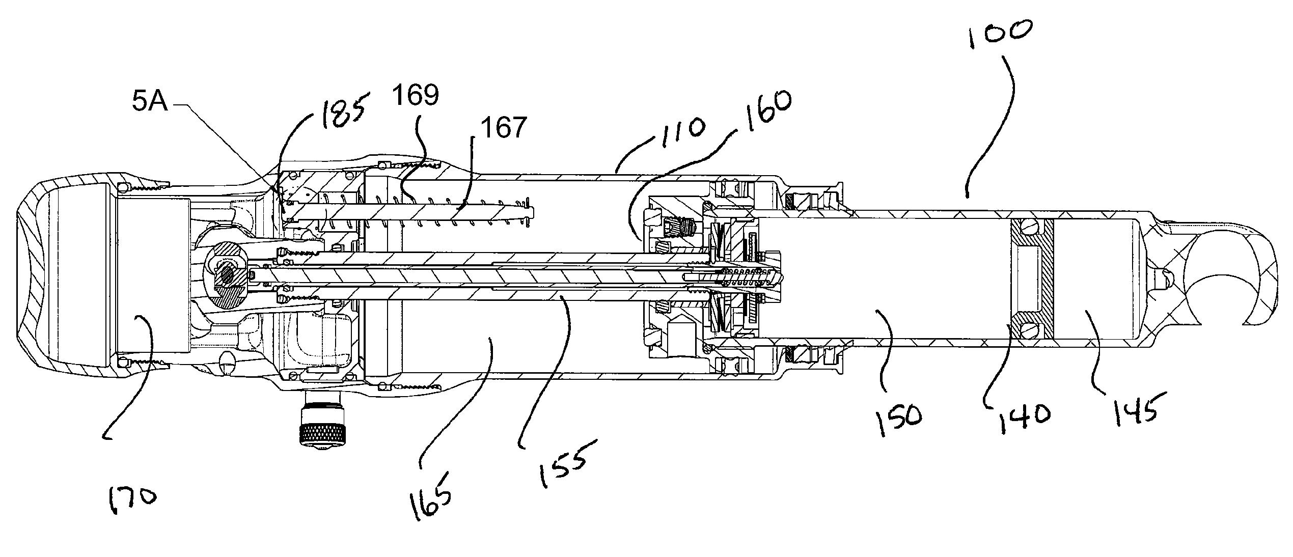
The invention relates to methods and apparatus for use in vehicle suspension. Specifically, it is about methods and apparatus related to adjustable spring rate and / or adjustable damping rate vehicle suspension. One embodiment involves a shock absorber with two gas chambers that are used for different parts of the suspension travel. Another embodiment involves an adjustment member that regulates the speed of travel between the gas chambers. Another embodiment involves a method of operating a shock absorber that regulates the speed of at least one of compression and decomposition of the gas chamber. Another embodiment involves a Schrader-type valve for filling the gas chamber with an equal pressure. The invention aims to improve the performance and comfort of vehicles during suspension travel.

Problems solved by technology

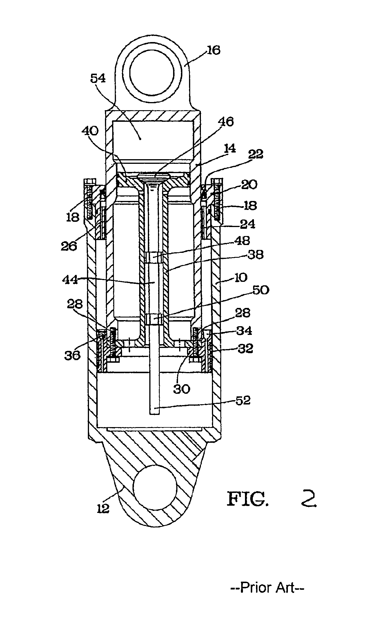
While the '364 reference teaches some basics of an air spring with dual chambers, it would be ineffective with many vehicle types.
In many vehicle types, such a design is would be unworkable since vehicles often operate on uneven surfaces where the gravitational forces cannot be relied upon to consistently open or close a valve (and may cause arbitrary opening and closing with no functional benefit).
Further, many vehicles include springs having axes mounted horizontally (or other non-vertical), upside down or at other angles inconsistent with gravity based operational features.
Moreover, the design illustrated in the '364 patent is limited to use with simple air-type springs and not with more sophisticated mechanisms that include fluidly isolated dampers.
However, there is no teaching as to how such a filling might take place, i.e., the pre-filling of essentially two separate chambers.

Method used


Image

  • Methods and apparatus for suspending vehicles
  • Methods and apparatus for suspending vehicles
  • Methods and apparatus for suspending vehicles

Examples


Embodiment Construction

[0027]In this disclosure the term “air” is used interchangeably with the term “gas” unless otherwise stated. Both terms generally indicate a compressible fluid. One embodiment comprises an air spring shock absorber for a vehicle. In one embodiment the vehicle is a bicycle. The air spring is advantageous because it includes at least two sequentially activated gas spring chambers that operate to increase the effective gas volume of the spring, at least one communication valve for opening a fluid flow path between the chambers, and a fill valve for selectively applying gas pressure within the chambers. In one embodiment the fluid path between the chambers is opened using a mechanical actuator and in another embodiment, a pressure actuated valve opens the fluid path between the chambers. In one embodiment, at least two air chambers can be filled from the same pressure inlet either simultaneously or sequentially as preferred. In one embodiment both chambers of a dual gas chamber gas spri...


PUM


Abstract

Embodiments of the invention generally relate to methods and apparatus for use in vehicle suspension. Particular embodiments of the invention relate to methods and apparatus useful for variable spring rate and / or variable damping rate vehicle suspension. In one embodiment, a shock absorber for a vehicle includes a gas spring having first and second gas chambers. The first chamber is utilized during a first travel portion of the shock absorber and the first and second chambers are both utilized during a second portion of travel. The shock absorber further includes a fluid isolated damper for regulating the speed of travel throughout both portions of travel.

Description

CROSS-REFERENCE TO RELATED APPLICATIONS[0001]This application claims benefit of U.S. provisional patent application Ser. No. 61 / 038,015, filed Mar. 19, 2008 and Ser. No. 61 / 157,541, filed Mar. 4, 2009, both of which are herein incorporated by reference.FIELD OF THE INVENTION[0002]Embodiments of the invention generally relate to methods and apparatus for use in vehicle suspension. Particular embodiments of the invention relate to methods and apparatus useful for variable spring rate and / or variable damping rate vehicle suspension.BACKGROUND OF THE INVENTION[0003]Vehicle suspension systems typically include a spring component or components and a damping component or components. Frequently those discrete components are separately mounted on a vehicle. Traditionally, mechanical springs, such as metal leaf or helical springs, have been used in conjunction with some type of viscous fluid based damping mechanism mounted functionally in parallel. More recently, compressed gas acting over a ...

Claims


Application Information

Patent Timeline
Patent Type & Authority Patents(United States)
IPC IPC(8): F16F9/48F16F9/342F16F9/06B60G17/048F16F5/00
CPCF16F9/486B60G2202/152B60G2500/22B60G2600/21B60G17/048B60G2300/12F16F9/063B60G2500/2064
Inventor WOOTTEN, DENNIS K.FOX, ROBERT C.HAUGEN, DAVID M.
Owner FOX FACTORY
Learn More