
System and method for controlling the position of a instrument cable towed in water

a technology of instrumented cables and systems, which is applied in the direction of instruments, process and machine control, electric devices, etc., can solve the problems of increased risk of instrumented cable entanglement, non-uniform distribution of forces acting perpendicular to the instrumented cables, and worst-case situations, so as to optimize the robustness of roll control

Active Publication Date: 2014-11-25
KONGSBERG DISCOVERY AS
View PDF17 Cites 4 Cited by
  • Summary
  • Abstract
  • Description
  • Claims
  • Application Information

AI Technical Summary

Benefits of technology

[0022]The main object of the invention is to provide a method and a system which completely or partly overcomes the disadvantages of the present solutions mentioned above. It is also an object to provide a method which can be used on several types of control devices for instrumented cables, but particularly for use of control devices including three or more wings. It is also an object of the present invention that the system and method shall make the instrumented cable to better withstand affection from uncontrollable forces in the environment around the instrumented cable. It is further an object of the system and method to reduce the power required for controlling. It is further an object of the present invention that it is shall provide opportunities to untwist / untangle twists applied to the instrumented cable. It is an object of the present invention that it shall allow faster course change operations and shorter finishing of operations, and shorter run-ins after line-turns and other operations to an approximately ideal position. An object of the invention is to provide a system and a method which can handle different fault situations / conditions which may arise, including taking into consideration the condition of the control devices.
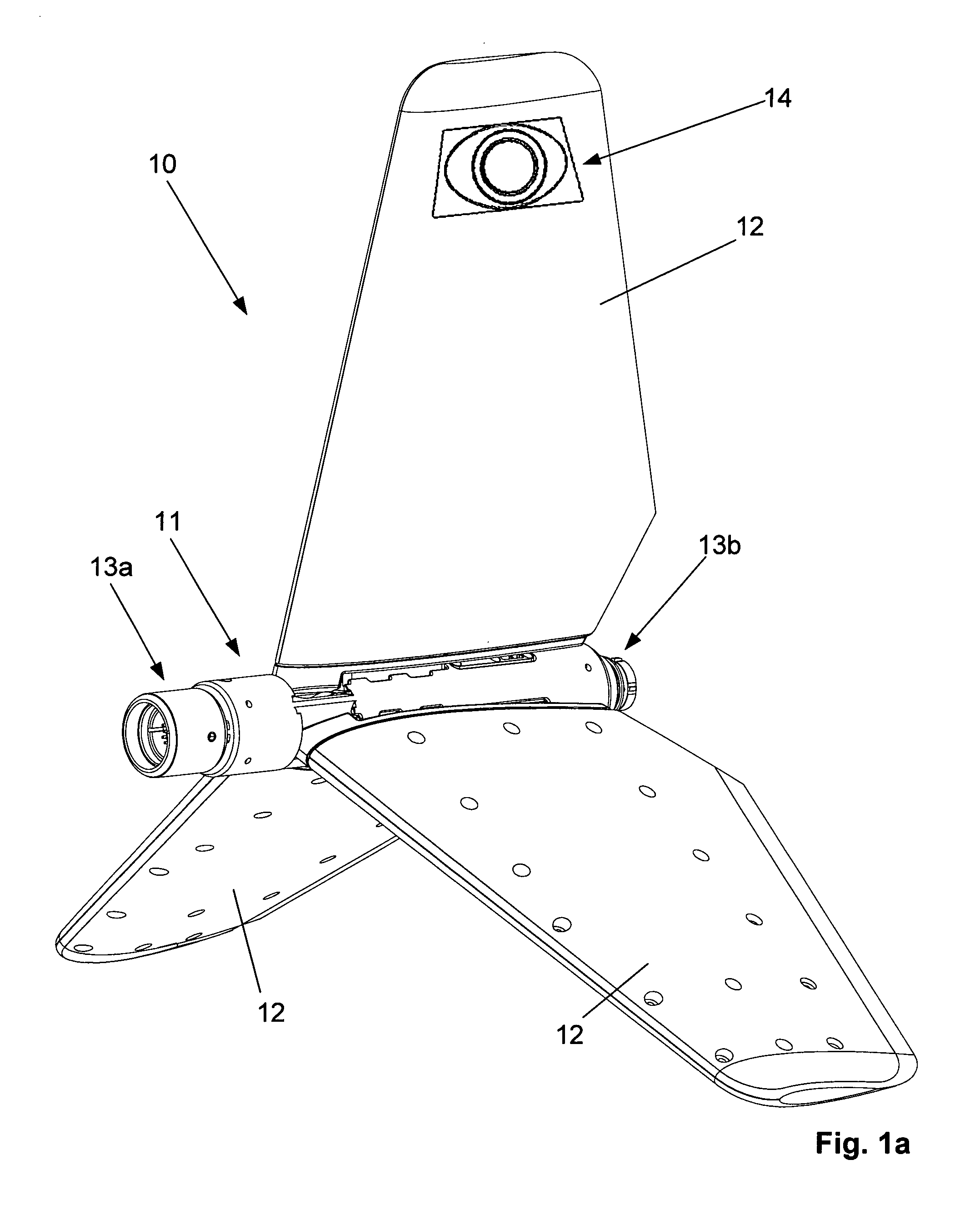
[0034]That means that the control devices are formed of a main body and at least three wings, so-called smart wings, or at least three motor and drive gear housings provided with wings. The term smart wing is used to illustrate that wing, power supply (batteries), processor unit, motor with momentum sensor, intelligent charging electronics, and hall effect sensor are integrated into the one and same unit, said wing being adapted to be detachably connected to the main body in a simple manner. The alternative which includes motor and drive gear housings is used to illustrate that power supply (batteries), processor unit, motor with momentum sensor, intelligent charging electronics and hall effect sensor, are integrated into the one and same unit, denoted as an motor and drive gear housing which again is provided with a wing, said motor and drive gear housings and wing forming a detachable unit which in a simple manner can be attached to and detached from the main body.
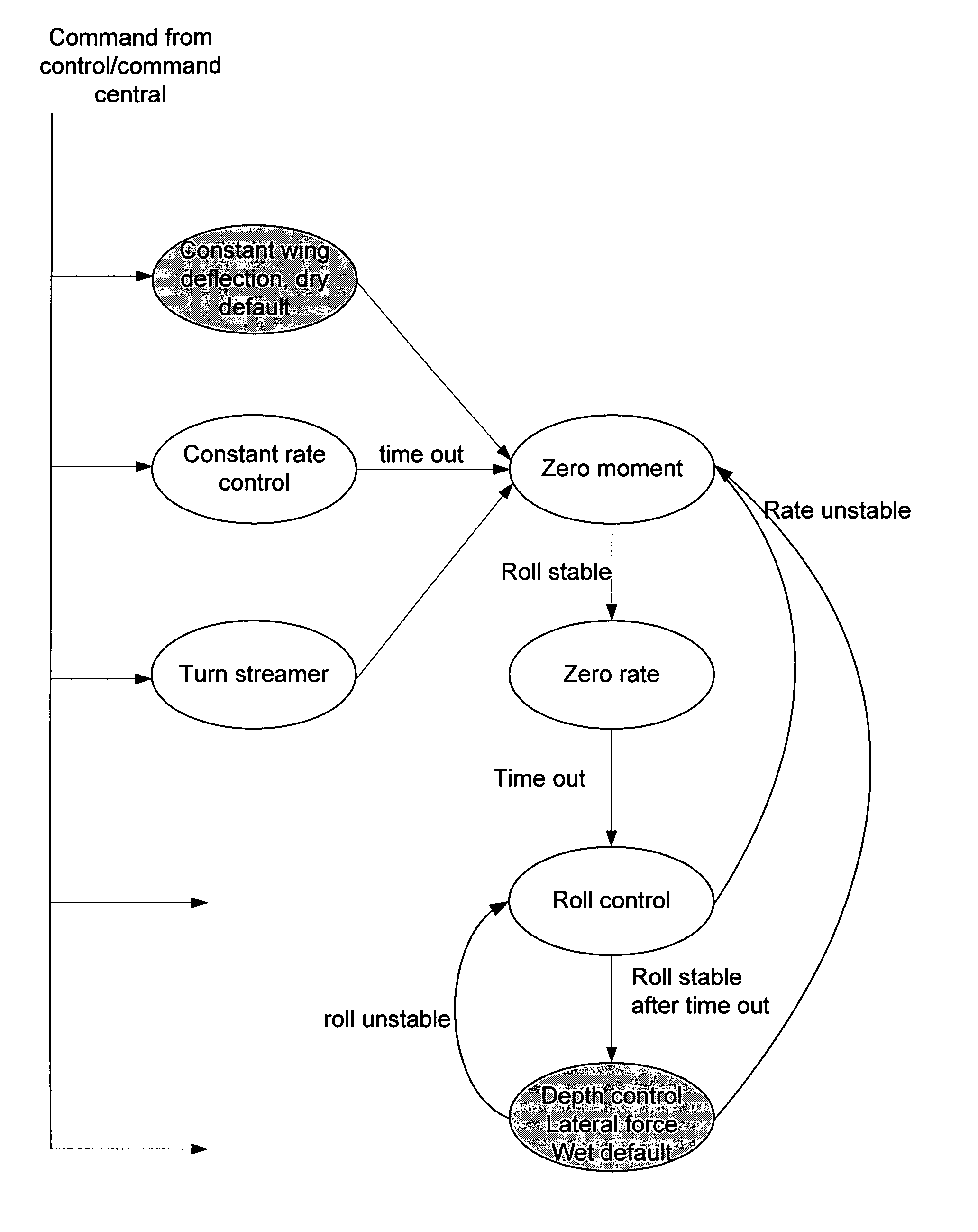
[0088]Depth control and lateral force control are examples of conditions including set points for roll control of the instrumented cable and the control device to a predefined roll angle. This reference roll angle depends on the wing distribution of the control device and is chosen to increase the roll control stability in combination with depth control and force control.
[0093]Pure depth control and depth control combined with lateral force control, either port or starboard, has different predefined roll angle references for control device and instrumented cable. These predefined reference angles are chosen to optimize the roll control robustness, which has been identified as a key factor in control of instrumented cables by using control devices.
[0112]By means of the present invention, a method and a system is achieved which increase the robustness in connection with controlling instrumented cables, for example in that reduced operative mode occurs at indication of damaged wings or other functional errors. By means of the system, depth control and / or roll control is maintained in cases where one or more wings have function fault.
[0114]By using range from a point close to the control device to be controlled, a more accurate calculation of distances and accordingly smaller deviations in measurements which result in a more accurate, robust and less energy demanding control.

Problems solved by technology

In general, the worst-case situation occurs when towing in the same direction as the swell.
In the case of both swell and cross-current influences, the risk of instrumented cable entanglement is therefore increased.
However, the forces acting perpendicular to the instrumented cables are non-uniformly distributed over the length of the cable and will change with time as the towed array moves forward.
This increases the time it takes to perform a survey, and therefore increases the cost of the survey.
However, because of sea currents the instrumented cables fail to accurately follow the path of the seismic survey vessel, sometimes deviating from this path at an angle, known as feathering angle.
This can adversely affect the coverage of the survey, frequently requiring that certain parts of the survey to be repeated.
In really bad circumstances, the cables can actually become entangled, especially at the end of the instrumented cables, which can cause considerable damage and considerable financial loss.
As control devices (in some of the publications mentioned above) are suspended under the instrumented cable, they produce substantial noise when they are towed through the water.
This is a relatively expensive and complex electromechanical construction which is very vulnerable in subsea operations.
This adds complexity to the local control loop of the total control system and results in bad stability properties as roll angle must be adjusted continuously according to changes in desired total force, particularly induced from the depth control.

Method used


Image

  • System and method for controlling the position of a instrument cable towed in water
  • System and method for controlling the position of a instrument cable towed in water
  • System and method for controlling the position of a instrument cable towed in water

Examples


Embodiment Construction

[0116]The invention is in the following described in further details with references to the drawings, where

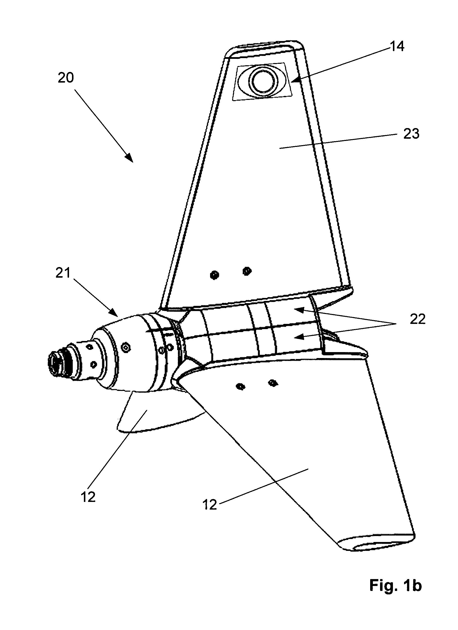
[0117]FIG. 1a-b show two different control devices for controlling instrumented cables,

[0118]FIG. 2 shows an example of a system according to the invention in operation,

[0119]FIG. 3 shows a block diagram for local control, and

[0120]FIG. 4 shows a block diagram for global control.

[0121]First referring to FIG. 1a-b which illustrate control devices 10, 20 for connection in series between two adjacent instrumented cable sections of a multi-sectional cable, for controlling the instrumented cable. FIG. 1a shows an embodiment where the control device 10 is formed of a main body 11 and three similar wings 12, so-called smart wings, which are evenly distributed about the main body 11, and is a so-called three axis bird. The main body 11 is substantially an elongate streamlined tubular housing, which at its ends includes connection means 13a and 13b adapted for mechanical and electrical ...


PUM


Abstract

System and method for controlling an instrumented cable (30) towed in water, such as a marine seismic streamer and / or an instrumented towed cable array (streamer array), to which at least one instrumented cable (30), control devices (10, 20) are arranged to control the individual instrumented cables (30) both in shape and position in relation to other instrumented cables (30) and then counteract cross currents and / or other dynamic forces affecting a towed cable array behind a seismic survey vessel (50). The wings (12, 23) of the control devices (10, 20) are provided with acoustic transmitter / receiver means (14) and electronics for acoustic ranging, and the vessel (50) and one or more tail buoys (60) are provided with acoustic transmitter / receiver means (62) and electronics for acoustic ranging, and is provided with instrumentation for absolute position and velocity.

Description

[0001]This application is a 371 of PCT / NO2010 / 000268, filed on Jul. 6, 2010, which is incorporated herein by reference.[0002]The invention relates to a method for positioning an instrumented cable towed in water, such as a marine seismic streamer and / or an instrumented towed cable array (streamer array) according to the preamble of claim 1.[0003]The invention also relates to a system for positioning an instrumented cable towed in water, such as a marine seismic streamer and / or an instrumented towed cable array (streamer array) according to the preamble of claim 13.BACKGROUND[0004]A seismic streamer is an elongated cable-like structure (typically up to several thousand meters long), which includes an array of hydrophone cables and associated electric equipment along its length, and which is used in marine seismic survey. In order to perform a 3D / 4D seismic survey, a plurality of such instrumented cables is towed behind a survey vessel. Acoustic signals are produced by the seismic sou...

Claims


Application Information

Patent Timeline
Patent Type & Authority Patents(United States)
IPC IPC(8): G01V1/20G01V1/38
CPCG01V1/3826G01V1/201G01V1/3835
Inventor FJELLSTAD, OLA ERIKRINNAN, ARNE
Owner KONGSBERG DISCOVERY AS
Learn More