

Device and method for cooling and dehumidifying room air
a technology for room air and devices, applied in stationary conduit assemblies, energy-efficient heating/cooling, heating types, etc., can solve the problems of affecting affecting the efficiency of the operation of these devices, so as to reduce prevent the formation of microeddies, and avoid hygiene problems
Active Publication Date: 2014-12-02
FRAUNHOFER GESELLSCHAFT ZUR FOERDERUNG DER ANGEWANDTEN FORSCHUNG EV
View PDF21 Cites 10 Cited by
- Summary
- Abstract
- Description
- Claims
- Application Information
AI Technical Summary
Benefits of technology
The present invention provides a device and method for cooling and dehumidifying air in a room, which avoids the drawbacks of conventional air conditioners such as noise and drafts. The device includes a processing unit that can handle a coolant suitable for dehumidifying and cooling air, a distribution unit for causing the coolant to flow past the air with direct contact, and a collecting unit for feeding coolant back to the processing unit. The device can cool and dehumidify the air simultaneously, and a thin liquid film can be created to efficiently cool or dehumidify the air. The coolant can also be mixed with additives to reduce vapor pressure and create a low-friction flow with low noise. Additionally, the device can be designed to prevent hygiene problems and absorb contaminants in the air.
Problems solved by technology
However, the operation of these devices is often associated with noise emissions and drafts.
However, cooling elements of this type have a limited cooling capacity.
Additionally, the temperatures of the cooling elements may not be kept too low, so as to avoid a separation of humidity present in the air, which would lead to mold formation.
Moreover, cooling elements of this type are not suitable for dehumidifying room air, since the separation of the humidity present in the air raises the danger of mold formation on the cooling element, as previously described.
However, a recirculation of air remains necessary to cool a room.
Method used
View moreImage
Smart ImageViewing Examples

Examples
Embodiment Construction
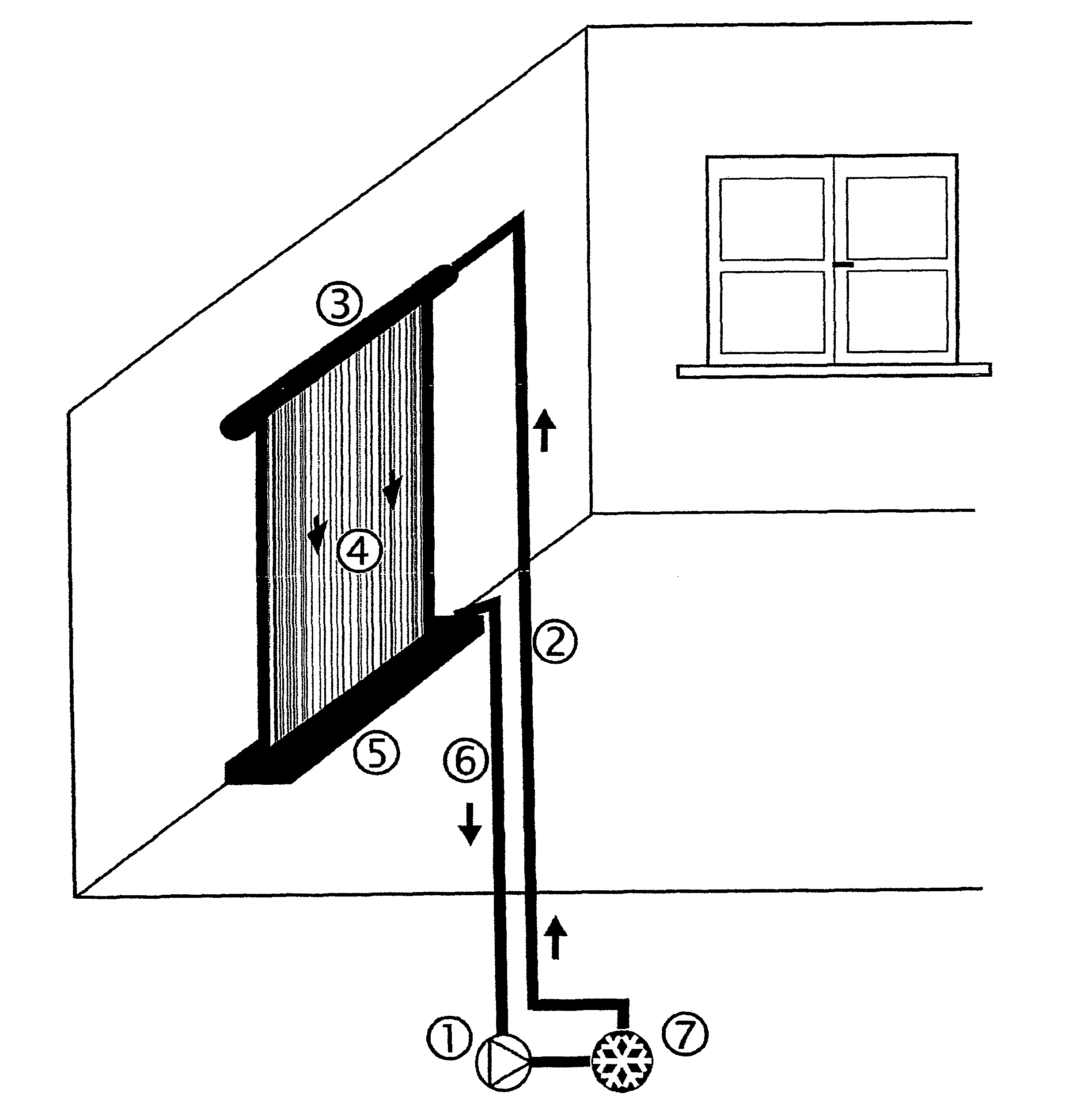
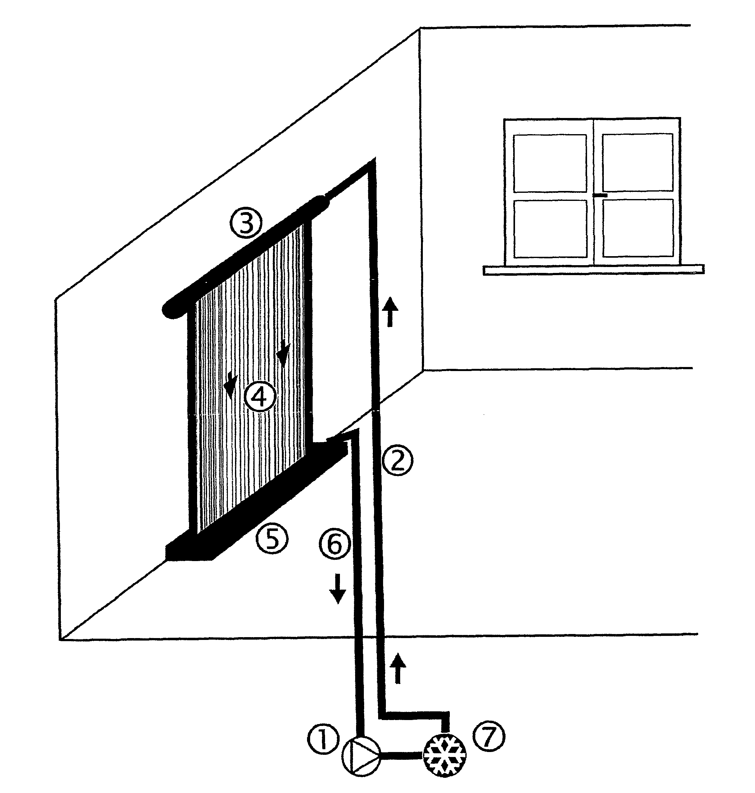
[0026]The sketch according to FIG. 1 is designed to explain an exemplary embodiment. Water is guided with the pump 1 through the feed line 2 to a horizontal pipe 3, which has an aperture slot on the underside. The water flows out through this aperture slot as a water film 4. A collecting tank 5 is attached below, from which the water is pumped back to the pump 1 through the drain line 6. The water is pumped again from the pump 1 to the feed line 2, during which it is cooled again in the cooler 7 arranged after the pump 2.
Login to View More PUM
 Abstract
The invention relates to a system and method for cooling and dehumidifying air in a room. The system includes a processing unit structured and arranged to process a coolant to achieve a cooling that exceeds cold due to evaporation, wherein the coolant cools and dehumidifies air coming into contact with the coolant. The system also comprises a distribution unit arranged to expose the coolant to the air and a collecting unit structured to feed the coolant that has come into contact with the air into the processing unit.
Description
CROSS-REFERENCE TO RELATED APPLICATIONS[0001]The present application is a U.S. National Stage of International Patent Application No. PCT / EP2006 / 007062 filed Jul. 18, 2006, and claims priority under 35 U.S.C. §119 of German Patent Application No. 10 2005 034 141.1 filed Jul. 19, 2005. Moreover, the disclosure of International Patent Application No. PCT / EP2006 / 00706 is expressly incorporated by reference herein in its entirety.BACKGROUND OF THE INVENTION[0002]1. Field of the Invention[0003]The invention relates to a device and method for cooling and dehumidifying room air.[0004]2. Discussion of Background Information[0005]Circulating air conditioners are primarily known from the prior art for heating and cooling room air in buildings. However, the operation of these devices is often associated with noise emissions and drafts. Therefore, water-bearing cooling elements such as, e.g., cooling ceilings have become established on the market. In cooling elements of this type, room air is c...
Claims
Login to View More Application Information
Patent Timeline
 IPC IPC(8): F25D17/06F24F6/00F24F5/00F24F1/00F24F3/14F24F1/0071
CPCF24F2003/144Y02B30/545F24F2006/003F24F5/0035F24F2001/0088F24F3/1417F24F2006/001F24F1/0007Y02B30/54F24F1/0071
InventorKUENZEL, HARTWIGSEDLBAUER, KLAUS
OwnerFRAUNHOFER GESELLSCHAFT ZUR FOERDERUNG DER ANGEWANDTEN FORSCHUNG EV