Cable connector and cable assembly, and method of manufacturing cable assembly

a technology of cable connectors and cable assemblies, which is applied in the direction of fixed connections, coupling device details, coupling device connections, etc., can solve the problems of manufacturing problems and the possibility of electrical characteristics variation among cables for differential signal transmission, and achieve the effect of reducing the number of parts and being convenient to conn

Active Publication Date: 2014-12-02
HITACHI METALS LTD
View PDF6 Cites 10 Cited by
  • Summary
  • Abstract
  • Description
  • Claims
  • Application Information

AI Technical Summary

Benefits of technology

[0008]A preferred aim of the present invention is to provide a cable connector, a cable assembly, and a method of manufacturing the cable assembly, whose electric characteristics are stabilized by suppressing elastic deformation of a cable for differential signal transmission and which is easily connectable by reducing the number of parts.
[0027]According to the present invention, the first ground contact and the second ground contact are provided on the connector board, the respective signal line contacts are provided thereon between the respective ground contacts through a space, the first arm portion and the second arm portion are provided so as to be integrally with end portions of the respective ground contacts protruded from a side wall portion of the connector board and so as to be mutually extend toward the respective signal line contacts, and the outer conductor is held by the respective arm portions under a state that the respective signal line conductors are arranged in the respective signal line contacts. In this manner, it is not required to swage a shield connection terminal so as to be along with a shape of the outer conductor as conventional, so that the electric characteristics can be stabilized by suppressing the elastic deformation of the cable for differential signal transmission. Also, the conventional shield connection terminal is not required, and therefore, the connection work between the outer conductor and the respective ground contacts can be simplified as reducing the number of parts. Further, the soldering connection work for electrically connecting the outer conductor with the respective ground contacts is not required, either, and therefore, thermal deformation of the cable for differential signal transmission due to exposure to a high temperature is prevented.

Problems solved by technology

However, since the shield connection terminal is swaged so as to be along with the shape of the outer conductor, the insulator inside the outer conductor is elastically deformed by a swaging force in some cases, which results in occurrence of a problem in manufacture such as change of a distance between the respective signal line conductors inside the insulator.
As a result, a problem of variation in electric characteristics among the cables for differential signal transmission may occur for each product.

Method used


Image

  • Cable connector and cable assembly, and method of manufacturing cable assembly
  • Cable connector and cable assembly, and method of manufacturing cable assembly
  • Cable connector and cable assembly, and method of manufacturing cable assembly

Examples


first embodiment

[0043]Hereinafter, the present invention will be described in detail with reference to the drawings.

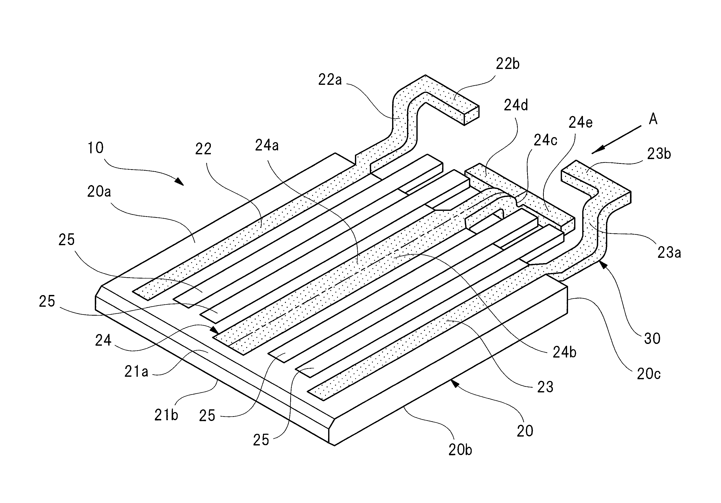
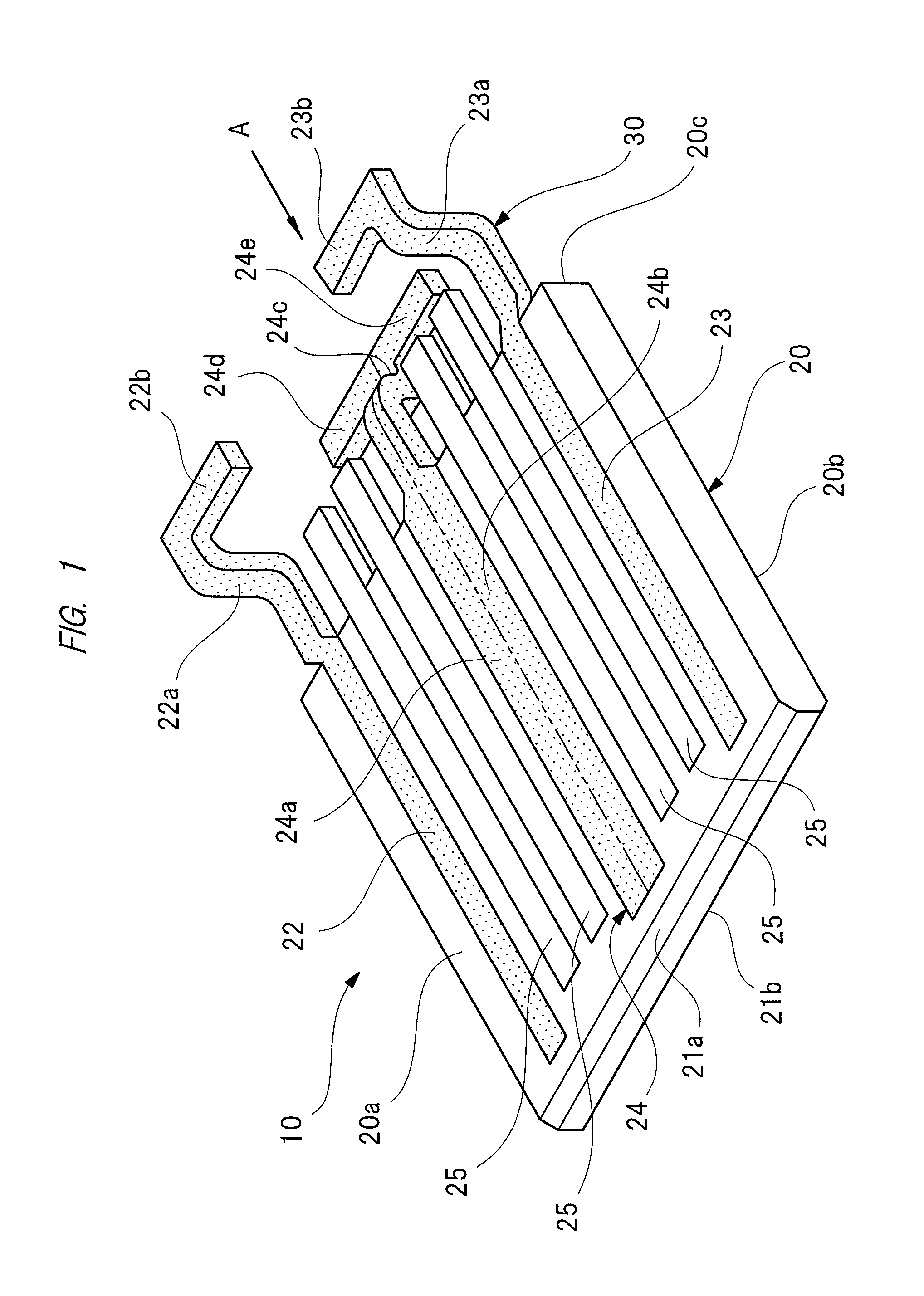
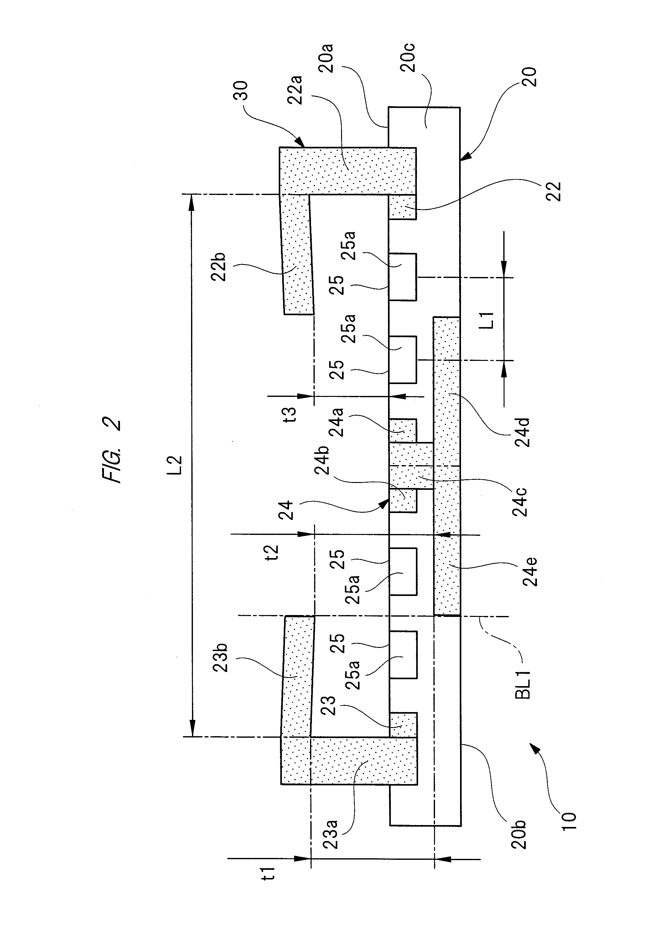
[0044]FIG. 1 is a perspective view illustrating a cable connector according to the first embodiment, FIG. 2 is a side view on an arrow “A” in FIG. 1, FIG. 3A is a perspective view of a cable for differential signal transmission, FIG. 3B is a cross-sectional view of the cable for differential signal transmission, FIGS. 4A and 4B are partially-enlarged views for explaining a manufacturing procedure (assembling procedure) of a cable assembly, FIG. 5 is a perspective view for explaining the manufacturing procedure of the cable assembly, and FIG. 6 is a side view on an arrow “B” in FIG. 5.

[0045]As illustrated in FIGS. 1 and 2, a cable connector 10 is provided with a connector main body (connector board) 20 and a cable connection portion 30. The connector main body 20 is configured to be inserted into, for example, a slot (socket) provided in a backplane product (not illustrated), and a plu...

third embodiment

[0104]FIG. 9 is a perspective view illustrating a cable connector according to the

[0105]As illustrated in FIG. 9, a cable connector 60 according to the third embodiment is different from the cable connector 10 according to the first embodiment (see FIG. 1) in only that holding reinforcement portions 61 to 64 extending in the longitudinal direction of the cable for differential signal transmission 40 are integrally provided with the front-side arm portions 22b and 23b and the rear-side arm portions 24d and 24e integrally provided with the respective ground contacts 22 to 24.

[0106]Here, since the respective holding reinforcement portions 61 to 64 are integrally provided with the front-side arm portions 22b and 23b and the rear-side arm portions 24d and 24e, they are arranged on the center portion CE of the cable for differential signal transmission 40 (see FIG. 4B).

[0107]Even in the cable connector 60 according to the third embodiment formed as described above, the same function effec...

fourth embodiment

[0109]FIG. 10 is a perspective view illustrating a cable connector according to the

[0110]As illustrated in FIG. 10, a cable connector 70 according to the fourth embodiment is different from the cable connector 10 according to the first embodiment (see FIG. 1) in only that two cable connectors 10 according to the first embodiment are arranged integrally with each other on boundary of a broken line “P” so as to provide slots SL1 to SL4. In this manner, four cables for differential signal transmission 40 are electrically connectable so as to correspond to the respective slots SL1 to SL4. However, the number of cable connectors 10 to be connected is not limited to two but is any number, and three or more cable connectors 10 may be arranged integrally with each other.

[0111]Even in the cable connector 70 according to the fourth embodiment formed as described above, the same function effect as that of the above-described first embodiment can be achieved.

[0112]Next, a fifth embodiment of th...


PUM

PropertyMeasurementUnit
angleaaaaaaaaaa
thicknessaaaaaaaaaa
elastic forceaaaaaaaaaa

Abstract

A cable connector and a cable assembly in which electrical characteristics are stabilized by suppressing elastic deformation of a cable for differential signal transmission, and besides, which are easily connectable by reducing the number of parts, and a method of manufacturing the cable assembly are provided. Respective ground contacts and respective signal line contacts positioned between the respective ground contacts through a space are provided in a connector main body. Front-side arm portions and rear-side arm portions mutually extending toward the respective signal line contacts are integrally provided with end portions of the respective ground contacts protruded from a side wall portion of the connector main body. And, under a state that respective signal line conductors are arranged in the respective signal line contacts, an outer conductor is held by the front-side arm portions and the rear-side arm portions.

Description

CROSS-REFERENCE TO RELATED APPLICATION[0001]The present application claims priority from Japanese Patent Application No. 2012-261954 filed on Nov. 30, 2012, the content of which is hereby incorporated by reference into this application.TECHNICAL FIELD OF THE INVENTION[0002]The present invention relates to a cable connector provided with a pair of signal line conductors and electrically connected with a cable for differential signal transmission which transmits differential signals whose phases are inverted to each other by an angle of 180°, relates to a cable assembly provided with the cable for differential signal transmission and the cable connector, and relates to a method of manufacturing the cable assembly.BACKGROUND OF THE INVENTION[0003]Conventionally, a differential interface standard such as LVDS (Low Voltage Differential Signal) is adopted in a device such as a server, a rooter, and a storage product, which handles a high-rate digital signal of several Gbit / s or higher, an...

Claims


Application Information

Patent Timeline
Patent Type & Authority Patents(United States)
IPC IPC(8): H01R43/26H01R12/62H01R12/55H01R43/02H01R9/03
CPCH01R43/0207H01R9/037H01R43/26H01R12/62Y10T29/49176Y10T29/49174H01R13/65917
Inventor NONEN, HIDEKIISHIMATSU, YOSUKE
Owner HITACHI METALS LTD
Why Eureka
Try Eureka