Light source device with light-emitting diode module

a technology of light-emitting diodes and light-emitting devices, which is applied in the direction of electric variable regulation, process and machine control, instruments, etc., can solve the problems of shortening the service life of leds and significant variation in current entering the light-emitting units, and achieve the effect of efficiently generating a stable curren

Active Publication Date: 2014-12-09
RUI TENG OPTO TECH
View PDF10 Cites 0 Cited by
  • Summary
  • Abstract
  • Description
  • Claims
  • Application Information

AI Technical Summary

Benefits of technology

[0007]Another objective of the present invention is to provide a low-cost light source device with an LED module.
[0014]Accordingly, a light source device of the present invention is characterized in that: a load module steadily consumes a voltage difference to allow a constant current controlling unit to control and maintain a constant output current value, supply a stable current to an LED module, protect the LED module against overcurrent-induced damage, and prevent the LED module from incurring variations otherwise caused by a tiny variation of the output voltage of a voltage source. The present invention further discloses a voltage-regulating unit, a constant current controlling unit, a voltage difference, a residual voltage value, and a safe voltage value to achieve the following advantages: the LED module of the light source device supplies a stable current; and the light source device has a low-cost voltage-regulating unit, such as a low-dropout (LDO) regulator, for use in generating a stable current efficiently.

Problems solved by technology

However, a slight fluctuation in the voltage from the DC voltage source 12 will result in significant variation in the current entering the light-emitting units 11.
The unstable current not only has a destabilizing effect on the luminance of light emitted by the LEDs 112 in the light-emitting units 11, but also causes the LEDs 112 to generate heat unsteadily, which may in turn shorten the service lives of the LEDs 112.

Method used


Image

  • Light source device with light-emitting diode module
  • Light source device with light-emitting diode module
  • Light source device with light-emitting diode module

Examples


Embodiment Construction

[0018]Objectives, features, and advantages of the present invention are hereunder illustrated with specific embodiments in conjunction with the accompanying drawings.

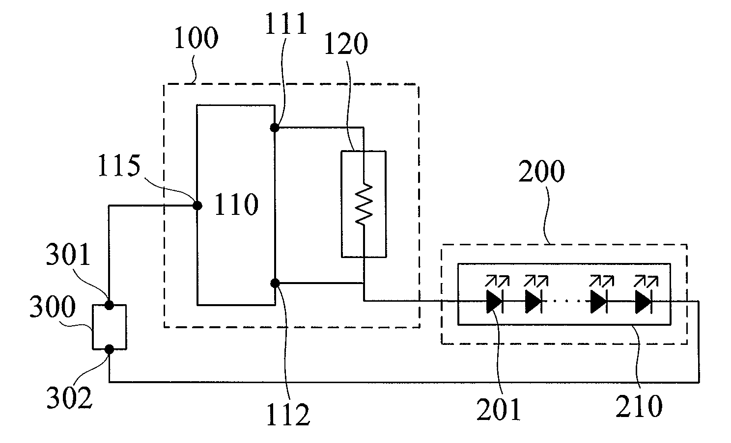
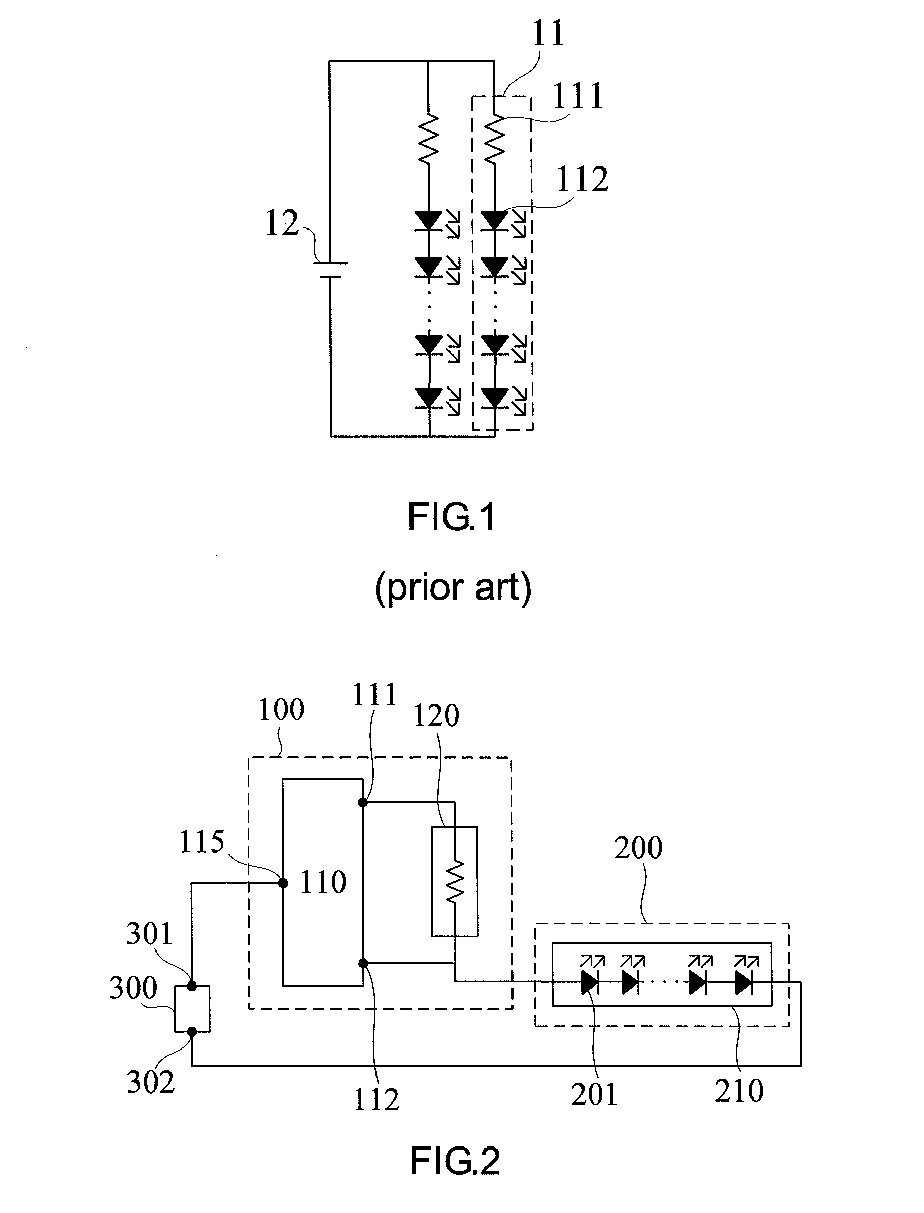
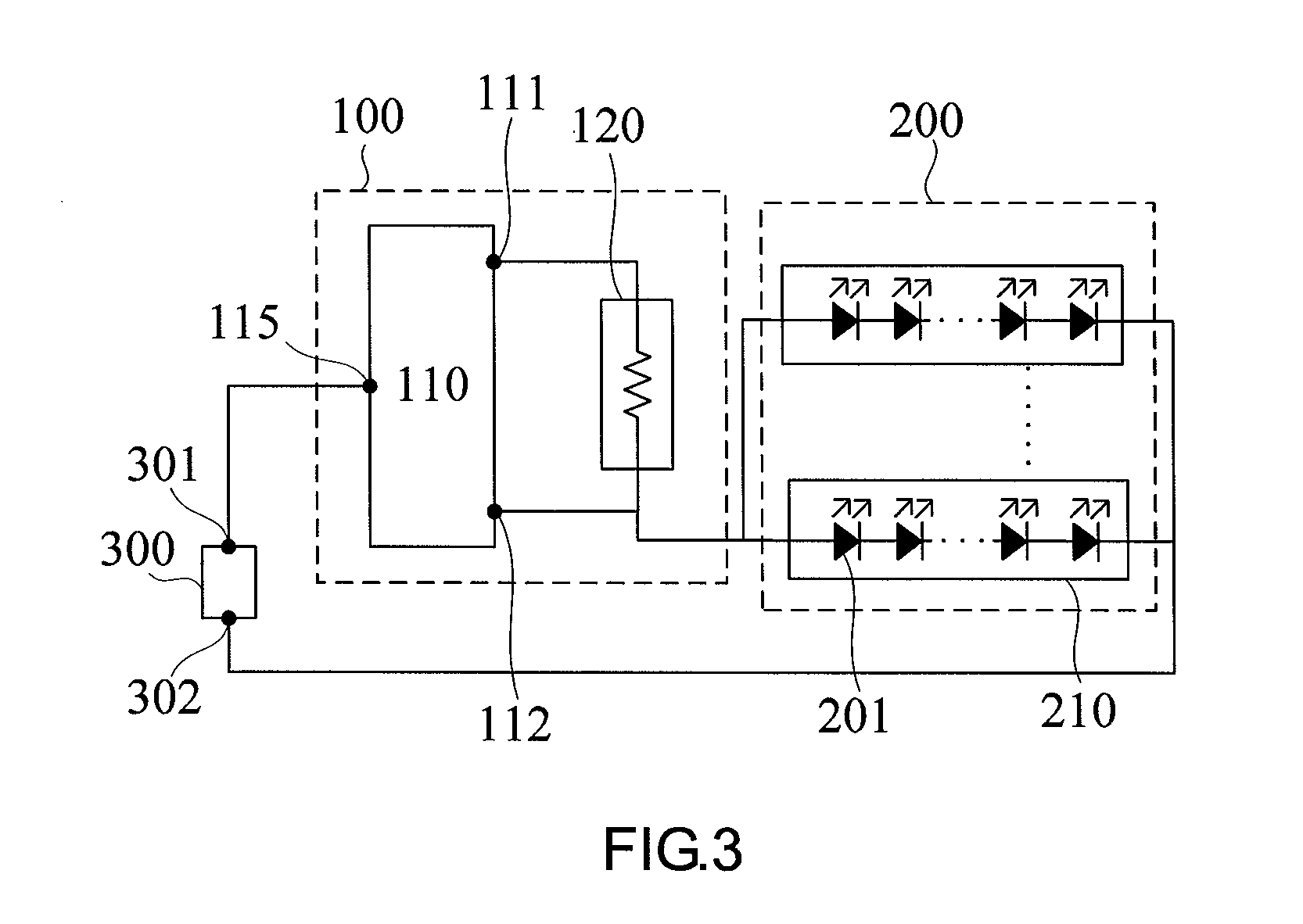
[0019]Referring to FIG. 2, there is shown a schematic view of a light source device with a light-emitting diode module (LED module) according to an embodiment of the present invention. According to the present invention, a light source device with a light-emitting diode module (LED module) comprises a load module 100 and an LED module 200. The load module 100 receives an output voltage from a voltage source 300 and controls the output voltage so as to supply a stable current to the LED module 200.

[0020]The load module 100 comprises a voltage-regulating unit 110 and a constant current controlling unit 120. The voltage-regulating unit 110 has an input end 115, a first output end 111, and a second output end 112. The input of the constant current controlling unit 120 is connected to the first output end 111, whereas the ou...


PUM


Abstract

A light source device with an LED module includes a load module. The load module includes a voltage-regulating unit and a constant current controlling unit parallel-connected between a first output end and a second output end of the voltage-regulating unit. An input end of the voltage-regulating unit is connected to a positive end of a voltage source. The voltage-regulating unit generates a stable voltage difference of less than 1.6V between the first and second output ends. The LED module receives a residual voltage equal to the result of subtracting from the output voltage of the voltage source the voltage difference consumed by the load module. The amount by which the residual voltage exceeds the operating voltage required for the entire LED string never exceeds safe voltage values. Even if a voltage source changes, the voltage-regulating unit can still generate a stable voltage difference and a stable current.

Description

CROSS-REFERENCE TO RELATED APPLICATION[0001]This application is a continuation-in-part (CIP) of co-pending U.S. application Ser. No. 13 / 289,526, filed on Nov. 4, 2011, which is a Continuation-in-Part of U.S. application Ser. No. 12 / 421,460, filed Apr. 9, 2009, now abandoned, for which priority is claimed under 35 U.S.C. §120; and this application claims priority of Application No. 097216582, filed in Taiwan, R.O.C. on Sep. 12, 2008, under 35 U.S.C. §119, the entire contents of all of which are hereby incorporated by reference.FIELD OF THE INVENTION[0002]The present invention relates to light source devices, and more particularly, to a light source device with a light-emitting diode module (LED module).BACKGROUND OF THE INVENTION[0003]FIG. 1 is a circuit diagram of a conventional LED light source module 10. As shown in the FIG. 1, the conventional LED light source module 10 includes a plurality of light-emitting units 11 each connected to a direct-current (DC) voltage source 12 in pa...

Claims


Application Information

Patent Timeline
Patent Type & Authority Patents(United States)
IPC IPC(8): H05B33/08H05B37/00H05B44/00
CPCH05B33/0806H05B33/0812H05B45/00H05B45/395Y02B20/30
Inventor CHANG, CHIH-YANG
Owner RUI TENG OPTO TECH
Why Eureka
Try Eureka