Method and apparatus for eliminating seam between adjoined screens

a technology of adjoined screens and seams, applied in the field of image display, can solve the problems of reducing screen size, difficult for users to gain a clear view of a reduced size screen, and unable to meet the requirements of display quality, so as to achieve no damage to image quality, no adverse effect on the portability of the device, and the effect of completely eliminating the seam

Active Publication Date: 2014-12-09
LENOVO (BEIJING) LTD
View PDF46 Cites 15 Cited by
  • Summary
  • Abstract
  • Description
  • Claims
  • Application Information

AI Technical Summary

Benefits of technology

[0025]In consideration of the above problems, the principal object of the present invention is to provide a method for eliminating a seam between adjoined screens and an apparatus thereof, which can completely eliminating the seam in the adjoined screen without any damage to images and significant increase in size and thickness of the screen.
[0054]As mentioned above, the present invention has the following advantages. By translating the image to the seam between the screens with help of the fiber means or the optical element, the seam can be completely removed. In addition, the translation process imposes no damage to the image quality, and the employed fiber means or optical element is small in size and mass, thereby no adversely effect on the device's own portability. The present invention can be realized with cheap materials in a simple manner without the need for massive and precise calculation. Thus it can be rapidly applied to a variety of products and result in considerable economical benefit.

Problems solved by technology

It is inevitable, however, that such computer minimization leads to a remarkable reduction in screen size, which makes it difficult for a user to gain a clear view of a reduced size screen.
In particular to the above data requiring a high display quality, a reduced size screen cannot meet the requirement for display quality.
This disables a user to acquire detailed information by a portable computer and accordingly causes inconvenience to the user.
Another example is that when a user processes stock data by a notebook computer, the user cannot obtain clearly huge stock information he desires due to a small screen, such as the overall tendency and detailed information on an individual share.
Although these portable devices are sufficiently capable of video data processing, with the limit on screen size, viewers cannot gain a visual enjoyment as that provided by a large screen.
Thus, the video data display ability of a portable device is degraded.
On the other hand, the manufacture cost increases and production technique becomes more complex as the size of a screen expands.
As for CRT adjoining, LCD adjoining, the dominant problem is that there is a seam between adjoined screens no matter how close the screens are brought to each other.
As a result of the edge width of each of CRT and LCD, a seam appears inevitably in the process of adjoining screens.
(1) This method can only reduce the width of a seam other than completely eliminating it. Even when this method is adopted, the edge of a screen can be still visible and the thus formed seam is about 1 mm in thickness. This is roughly acceptable for a large screen display, while for the case of adjoining small screens in potable devices, it can be hardly accepted. Since small screens are generally adjoined for a portable device and the eyes of a user are close to the screen of the portable device, even a slight gap can appear obvious. This degrades image quality and further provokes the user's discontentment.
(2) If this method is adopted, since the optical lens placed on the screen is thick, the screen increases in size and mass while deteriorates in portability. For example, if two LCDs are combined, the seam between them is 10 mm wide, and the optical lens above them is 25 mm thick. The optical lens of such thickness will apparently adds the size and mass of the screen and makes it less convenient to carry.
(3) Since this method compresses and magnifies the image at the edge, the image itself will be damaged.
Besides, this method requires a precise calculation for the area of the edge image to be compressed and magnified, thereby making it complex to implement and unsuitable for practical applications.
(1) In order to acquire a proper magnification factor, the Frensnal lens must be located a distance from the screens 20, otherwise the image cannot be magnified. This leads to a thicker display with an increased size, thereby worsening the portability of a device configured by this method.
(2) Bending the light through the Frensnal lens gives rise to a retrace phenomenon, therefore, in order to obtain the effect of a magnifier, fine zigzagged concentric circle strips must be spread over the lens surface. Such strips will adversely affect images and thereby image quality.
Besides, the processing cost for Frensnal lens is high, thus a high price hinders its application to a wide range.

Method used


Image

  • Method and apparatus for eliminating seam between adjoined screens
  • Method and apparatus for eliminating seam between adjoined screens
  • Method and apparatus for eliminating seam between adjoined screens

Examples


first embodiment

The First Embodiment

[0086](1) The Specific Process in Step 301

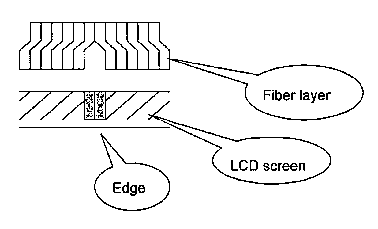
[0087]Considering the case of only adjoining two screen in the first embodiment of the present invention, fiber means is provided as shown in FIG. 4, and tilted fiber in this means are used to translate a respective image displayed on each of the screens to the position of the seam. In this embodiment, Step 301 includes:

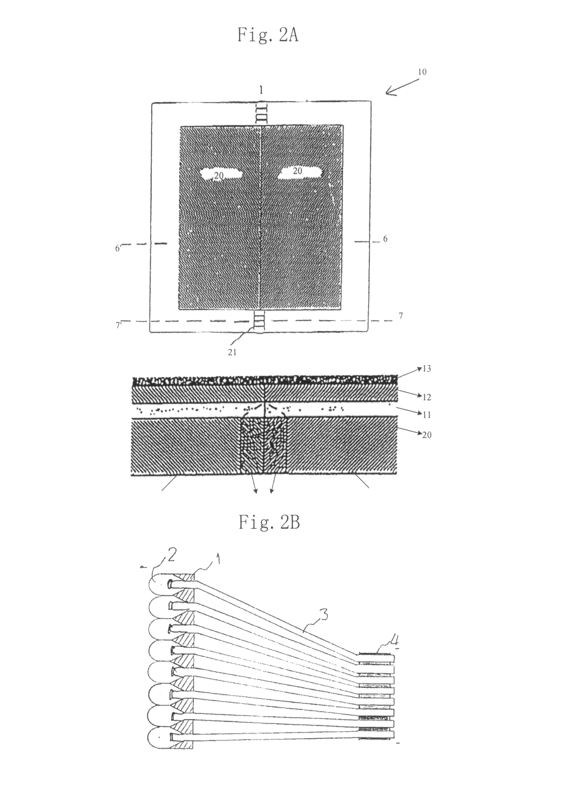
[0088]Step 3011: determining the number of fibers in the fiber means. Specifically, the whole image displayed on the two screens is divided pixel by pixel and each of the pixels is acquired by a corresponding fiber in the fiber means. Therefore, the number of the fibers in the fiber means is determined by providing the fibers in such a manner that each of the fibers corresponds to one ore more pixels to be transmitted via the fiber. In other embodiments of the present invention, one pixel can be transmitted via several corresponding fibers, and the number of the fibers in the fiber means can be determined ...

second embodiment

The Second Embodiment

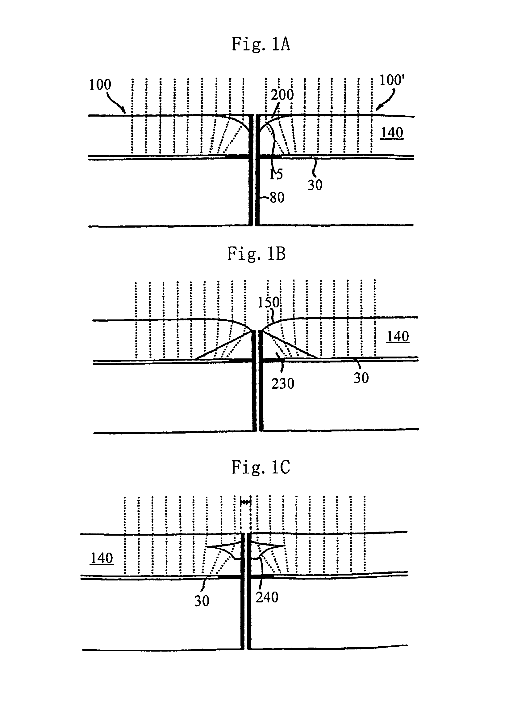
[0096]The first embodiment realizes only the elimination of a seam between two screens. Referring to FIG. 6, in the second embodiment, the interval between two pixels is extended through a fiber, and the image obtained after this extension can cover a seam among a plurality of screens. As a result, the seam is eliminated during the process of adjoining the plurality of screens.

[0097](1) The Specific Process in Step 301

[0098]Step 301a: determining the number of fibers in fiber means in the same manner as that described in the above step 3011;

[0099]Step 301b: determining the size of the seam among the screens, and extending the interval between the second ends of the fibers in the fiber means based on the determined size of the seam, so the image transmitted via the fiber means can cover the seam.

[0100]Referring to FIG. 7, a corresponding pixel of an image is acquired by the first end of each of the tilted fibers and then transmitted to the second end of the fiber...

third embodiment

The Third Embodiment

[0112](1) The Specific Process in Step 1001

[0113]In order to achieve a better effect for image translation, in Step 1001, the whole image is divided by a dividing unit that is the sectional shape of the incident end of a translation unit in the optical element. As a result, the parts of the divided image each have approximately the same size as that of the incident end of the translation unit, and the translation unit in the optical element can obtain sufficiently corresponding part of the divided image, thereby improving the translation quality.

[0114]Referring to FIG. 11A to 11D, an original image is shown in FIG. 11A. If the incident end of the translation unit has a bar shape, the original image can be divided into bars as shown in FIG. 11B; if the incident end of the translation unit has a square shape, the original image can be divided into squares as shown in FIG. 11C; if the incident end of the translation unit has a circular shape, the original image can ...


PUM

PropertyMeasurementUnit
acute angleaaaaaaaaaa
thicknessaaaaaaaaaa
widthaaaaaaaaaa

Abstract

A method for eliminating a seam between adjoined screens includes step A: acquiring an original image and adapting the acquired image to an image translation in subsequent step B; step B: translating the acquired image toward the position of the seam; and step C: reverting the translated image to the original one. An apparatus for eliminating a seam between adjoined screens includes an image acquisition module, an image translation module and an image reversion module. The image acquisition module is configured for acquiring an original image and transmitting the acquired image to the image translation module. The image translation module is configured for translating the received image toward the position of the seam so as to cover the seam by the translated image. The image reversion module is configured for receiving the translated image from the image translation module and reverting the image to the original one.

Description

BACKGROUND OF THE INVENTION[0001]1. Field of Invention[0002]The present invention relates to the field of image displaying, and more specifically, to a method for eliminating a seam between adjoined screens and an apparatus thereof.[0003]2. Description of Prior Art[0004]Recently, an increasing number of computers tend to the development of minimization with the continuous progress of electronic information technology. Accompanying the minimization, data-processing capability of computers has been enhanced, and a wider range of data types can be processed. Small-sized portable computers can be employed to fulfill such tasks as processing, storage and assembling for massive data, thereby significantly facilitating our daily work and life. For example, a notebook computer can be utilized to process stock information, map data and image data and display contents corresponding to the processing result on its screen. It is inevitable, however, that such computer minimization leads to a re...

Claims


Application Information

Patent Timeline
Patent Type & Authority Patents(United States)
IPC IPC(8): G09G3/20H04N9/31G09G3/36G09G5/00H04N9/12G02F1/1335G02F1/1333G09F9/30
CPCG09G3/3611G09F9/30H04N9/3147H04N9/12G02F1/133524G09G2320/02G09G2300/026G09G3/20G02F1/13336G02F1/1333G03B21/56H04N5/64H04N5/74
Inventor LI, ZHONGQING
Owner LENOVO (BEIJING) LTD
Why Eureka
Try Eureka