Detecting driver grip on steering wheel

a technology for steering wheels and drivers, applied in steering initiations, instruments, vessel construction, etc., can solve problems such as unsafe autonomous components, and achieve the effect of increasing the determination accuracy and increasing the determination accuracy

Active Publication Date: 2014-12-09
WAYMO LLC
View PDF7 Cites 211 Cited by
  • Summary
  • Abstract
  • Description
  • Claims
  • Application Information

AI Technical Summary

Benefits of technology

[0008]In another example, the method also includes, before moving the steering wheel, performing calibration based on a characteristic of the driver thereby increasing the accuracy of the determination of whether the driver is gripping the steering wheel. I

Problems solved by technology

In some situations, the autonomous vehicle may require the driver to take control of some aspect of control, such as during heavy traffic, poor sensor conditions, etc.
For example, it may be very unsafe for the autonomous com

Method used


Image

  • Detecting driver grip on steering wheel
  • Detecting driver grip on steering wheel
  • Detecting driver grip on steering wheel

Examples


Embodiment Construction

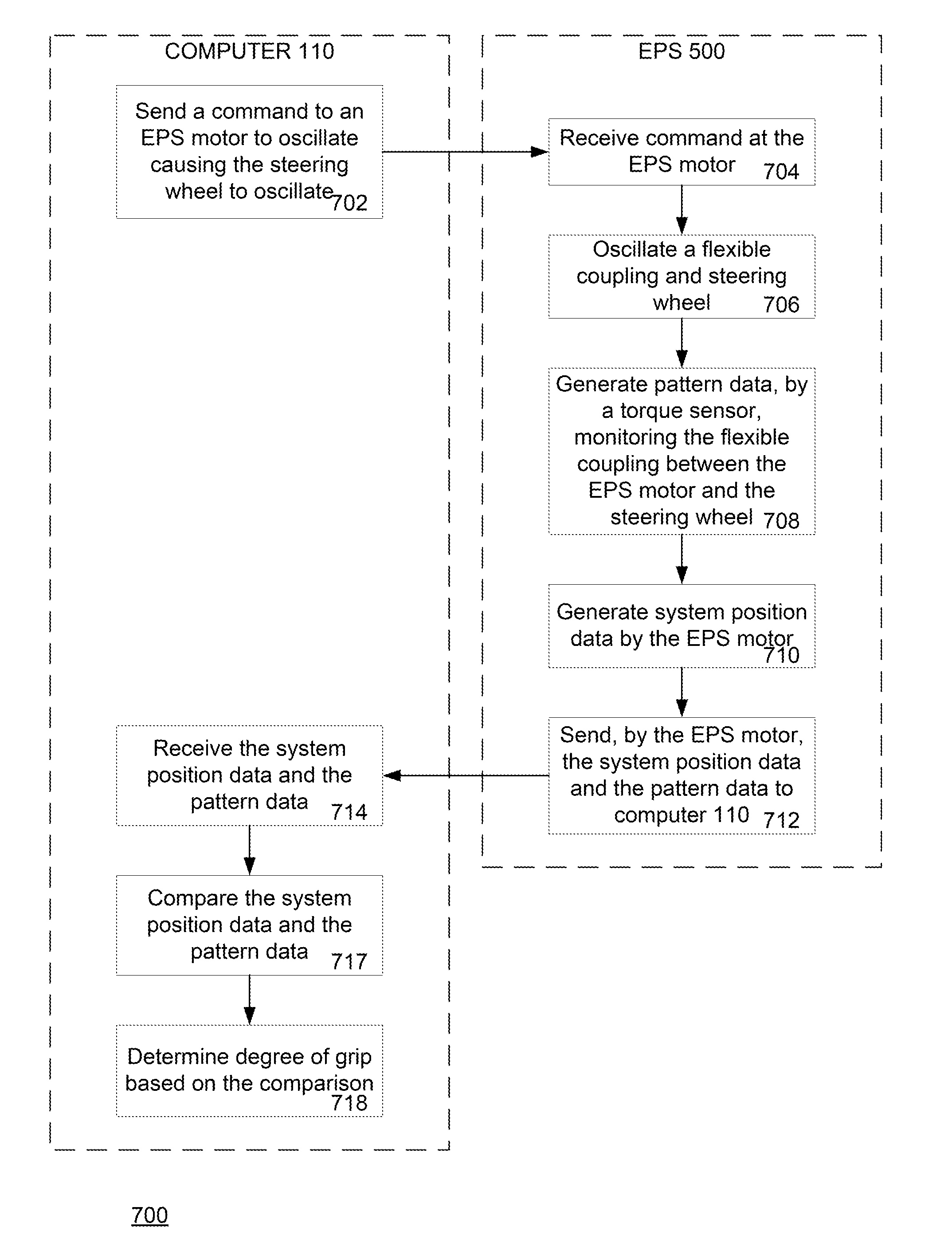
[0021]The disclosure relates generally to determining whether and by what degree a driver is gripping a steering wheel. In one aspect, in order to measure the driver's grip, a computer may send an electrically assisted power steering system (EPS) motor an excitation command to move the steering wheel. The EPS system may receive this information at the EPS motor, and the EPS motor may respond by moving, for example oscillating, a flexible coupling between the steering wheel and the EPS motor. The movement of the flexible coupling may also cause a corresponding an excitation movement at the steering wheel.

[0022]A torque sensor may generate pattern data by monitoring the flexible coupling between the EPS motor and the steering wheel. The EPS motor may also generate system position data for the excitation motion of the steering system. The pattern data and the system position data may be sent by the EPS motor and received by the computer. The computer may then compare the system positio...


PUM


Abstract

Aspects of the disclosure relate generally to determining by what degree a driver is gripping a steering wheel. In one example, a computer may send an electrically assisted power steering system (EPS) motor an excitation command to move. The EPS motor may respond by moving a flexible coupling between the steering wheel and the EPS motor. This may cause a corresponding movement at the steering wheel. A torque sensor may generate pattern data by monitoring the flexible coupling during the movement. The EPS motor may generate system position data for the entire steering system, for example, from the tires to the steering wheel. The pattern data and the system position data may be compared by the computer to determine the degree of grip. In this regard, the computer may determine the degree of a driver's grip without the need for additional sensors.

Description

BACKGROUND[0001]Autonomous vehicles use various computing systems to aid in the transport of passengers from one location to another. Some autonomous vehicles may require an initial input or continuous input from an operator, such as a pilot, driver, or passenger. Other autonomous systems, for example autopilot systems, may be used only when the system has been engaged, which permits the operator to switch from a manual mode (where the operator exercises a high degree of control over the movement of the vehicle) to an autonomous mode (where the vehicle essentially drives itself) to modes that lie somewhere in between.[0002]In some situations, the autonomous vehicle may require the driver to take control of some aspect of control, such as during heavy traffic, poor sensor conditions, etc. When the driver in an autonomous vehicle is prompted to take control there is an immediate need to establish if the driver has actually done so satisfactorily. For example, it may be very unsafe for...

Claims


Application Information

Patent Timeline
IPC IPC(8): B62D6/00
CPCB62D6/00B62D15/025B62D1/04B62D5/0481B62D6/008B62D6/10
Inventor LOMBROZO, PETER, CRAIG
Owner WAYMO LLC
Why Eureka
Try Eureka