Fixing device and image formation apparatus

a technology of fixing device and image formation apparatus, which is applied in the direction of electrographic process apparatus, instruments, optics, etc., can solve the problems of low mechanical strength, inability to meet the needs of use, so as to achieve the effect of adequate mechanical strength and heat generation efficiency

Active Publication Date: 2014-12-16
KONICA MINOLTA INC
View PDF13 Cites 0 Cited by
  • Summary
  • Abstract
  • Description
  • Claims
  • Application Information

AI Technical Summary

Benefits of technology

[0012]The present invention is made in view of the problems described above, and aims to provide a fixing device including a fixing member effectively self-adjusting the amount of heat generation and having adequate mechanical strength and heat generation efficiency. The present invention also provides an image formation apparatus provided with the same.

Problems solved by technology

Permalloy, however, does not have a high mechanical strength, and there is a problem that a fixing member using permalloy is likely to be damaged.
If annealing is performed on the entire fixing member containing permalloy, the mechanical strength of copper contained in the induction heat generator layer will be degraded as well as the mechanical strength of the permalloy, and it is impossible to obtain the strength required by a fixing member for a fixing device.
Although there is an option to first perform annealing on permalloy alone and then to form the heat generator layer by electrolytic plating, annealing forms a hard oxide layer on the surface of permalloy, and it is therefore difficult to obtain necessary peel strength between the heat generator layer and the permalloy.
However, if the reinforcing layer is adequately formed on the surface closer to the excitation coil in order to secure the mechanical strength, the heat generation efficiency will be degraded.

Method used


Image

  • Fixing device and image formation apparatus
  • Fixing device and image formation apparatus
  • Fixing device and image formation apparatus

Examples


Embodiment Construction

[0022]The following describes an embodiment of a fixing device and an image formation apparatus pertaining to the present invention, with reference to the drawings.

[1] Structure of Image Formation Apparatus

[0023]First, the following describes the structure of an image formation apparatus pertaining to the present embodiment.

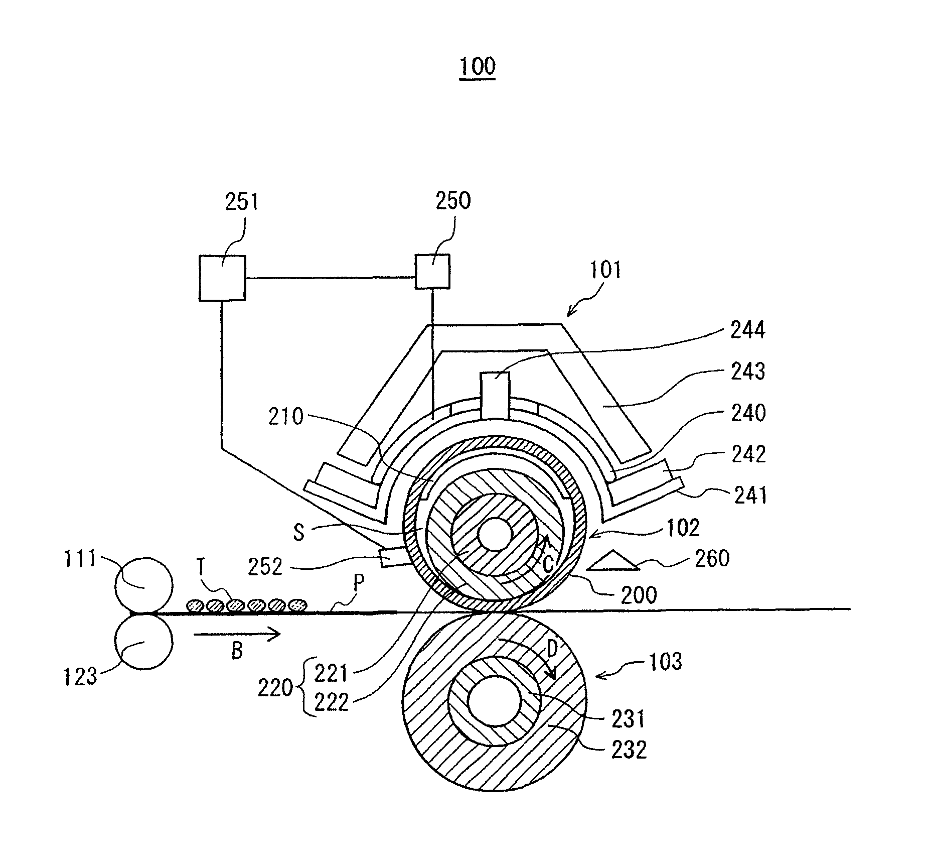
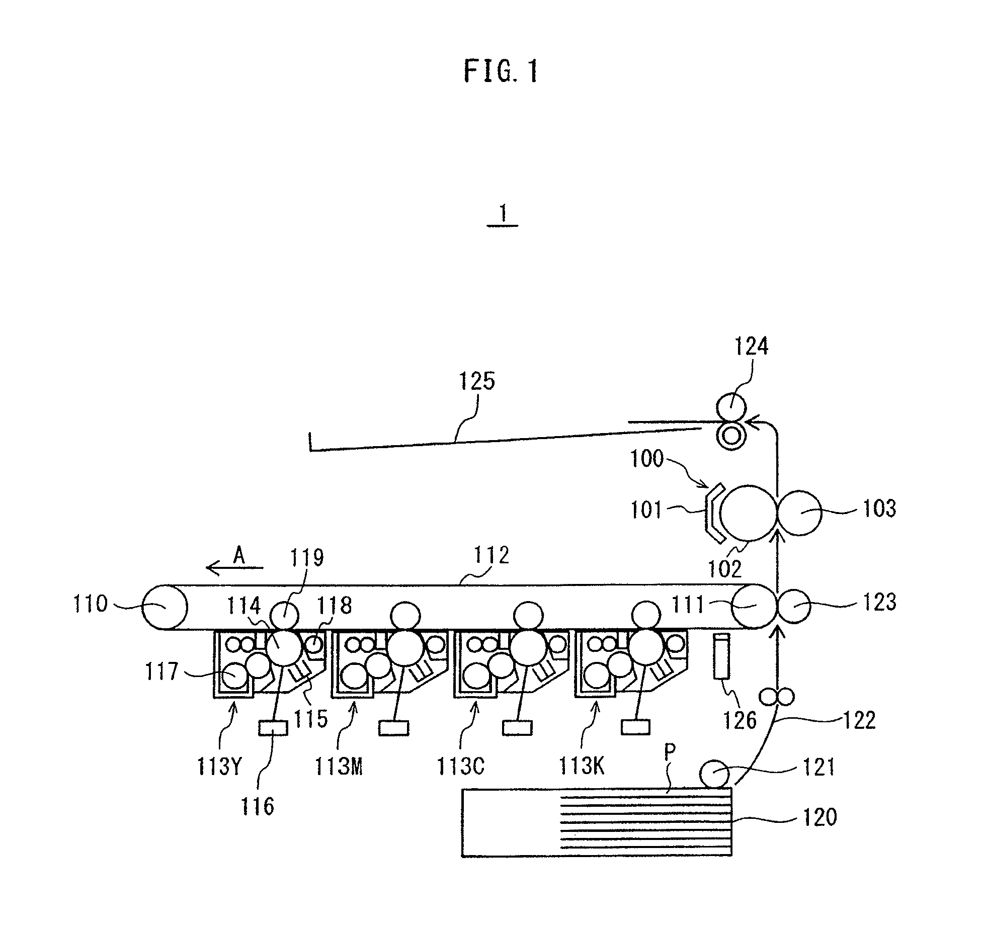
[0024]FIG. 1 shows primary components of the image formation apparatus pertaining to the embodiment. As shown in FIG. 1, the image formation apparatus 1 is a tandem color printer, and is provided with an intermediate transfer belt 112, which is suspended with tension between a drive roller 110 and a passive roller 111 and is rotated in the direction indicated by the arrow A in the drawing. The image formation apparatus 1 is also provided with image formation sections 113Y-113K which are arranged along the portion of the intermediate transfer belt 112 extending from the drive roller 110 to the passive roller 111. The image formation sections 113Y-113K respectively...


PUM


Abstract

A fixing device comprising: an endless fixing belt having a multilayer structure including a non-magnetic conductive layer and a first magnetic conductive layer, the non-magnetic conductive layer having a thickness smaller than a skin depth of a material thereof, the first magnetic conductive layer having a thickness smaller than a skin depth of a material thereof and being located farther from an outside surface of the fixing belt than the non-magnetic conductive layer; and a supporting member disposed inside the endless fixing belt and including a second magnetic conductive layer having a thickness larger than a skin depth of a material thereof. The first magnetic conductive layer and the second magnetic conductive layer have a higher specific resistance than the non-magnetic conductive layer, and the first magnetic conductive layer has been manufactured by plastic forming or plating.

Description

CROSS-REFERENCE TO RELATED APPLICATIONS[0001]This application is based on application No. 2011-191362 filed in Japan, the contents of which are hereby incorporated by reference.BACKGROUND OF THE INVENTION[0002](1) Field of the Invention[0003]The present invention relates to fixing devices and image formation apparatuses, and in particular to technology of improving both mechanical strength and heat generation efficiency of a fixing member, the fixing member being included in a fixing device that uses electromagnetic induction heating, and self-adjusting the amount of heat generation.[0004](2) Related Art[0005]Conventionally, there has been a known technology of reducing energy consumption of a fixing device that uses electromagnetic induction by reducing warm-up time of the fixing device and omitting preheating during the stand-by period. According to this technology, a part of fixing member with a small thermal capacity, such as a belt, is caused to generate Joule heat by electroma...

Claims


Application Information

Patent Timeline
Patent Type & Authority Patents(United States)
IPC IPC(8): G03G15/20
CPCG03G15/2053
Inventor YONEKAWA, NOBORU
Owner KONICA MINOLTA INC
Why Eureka
Try Eureka