
Two-rear-wheel electric vehicle

a technology of electric vehicles and rear wheels, which is applied in the direction of cycle equipment, transportation and packaging, cycle equipment, etc., can solve the problems of increasing the weight of the battery, affecting the service of delivery, and increasing the power consumption, so as to reduce the impact, reduce or prevent the increase in the weight of the vehicle body frame, and increase the battery size

Inactive Publication Date: 2014-12-23
YAMAHA MOTOR CO LTD
View PDF15 Cites 6 Cited by
  • Summary
  • Abstract
  • Description
  • Claims
  • Application Information

AI Technical Summary

Benefits of technology

The patent text describes a two-rear-wheel electric vehicle that reduces the weight of the vehicle body while maintaining a large battery capacity. This is achieved by reducing the angle formed between the direction in which an impact is transmitted from the rear wheel to the vehicle body frame via the shock absorber and the direction in which the bottom portion of the vehicle body frame extends. This reduces the bending load that is applied to the vehicle body frame when an impact occurs, which helps prevent an increase in the weight of the vehicle body frame. Additionally, the vehicle body frame includes a battery support portion that reduces the load applied to the battery, making it easy to increase the battery capacity without increasing the weight of the vehicle body. Overall, this design helps achieve a weight reduction of the vehicle body while ensuring a large battery capacity.

Problems solved by technology

For example, in a case where a user, when carrying out a delivery service, notices that a remaining battery charge of the electric vehicle is low but there is no time for charging, the delivery service may be disabled.
Similarly, the electric vehicle may force the user to refrain from the use thereof when the remaining battery charge is low.
An increase in the weight of the vehicle body leads to an increase in power consumption.
However, using a large-size battery for the increase in the battery capacity causes not only an increase in the weight of the battery but also the need to increase the weight of the vehicle body frame because the rigidity of the vehicle body frame must be ensured, which results in a further increase in the weight of the vehicle body.
Additionally, an increase in the weight of the vehicle body makes the handling of the vehicle body difficult, which deteriorates the convenience.
Therefore, how to achieve a weight reduction of the vehicle body while ensuring a large battery capacity is a problem.

Method used


Image

  • Two-rear-wheel electric vehicle
  • Two-rear-wheel electric vehicle
  • Two-rear-wheel electric vehicle

Examples


Embodiment Construction

[0040]Hereinafter, a two-rear-wheel electric vehicle according to various preferred embodiments of the present invention will be described with reference to the drawings.

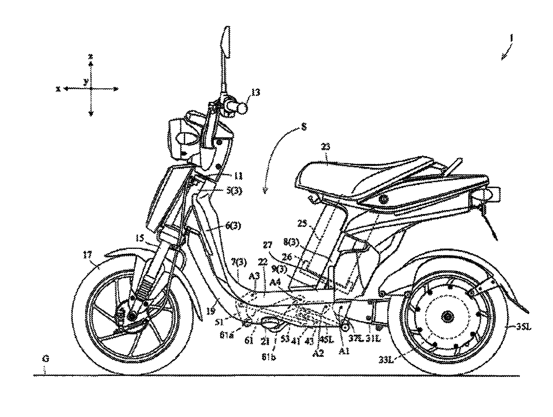
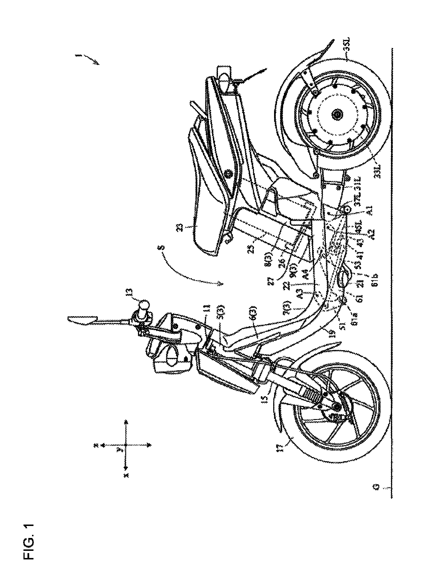
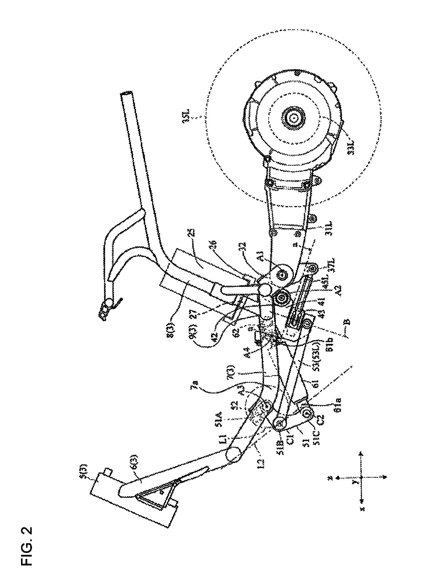
[0041]FIG. 1 is a left side view of an electric vehicle according to a preferred embodiment of the present invention. FIG. 2 is a left side view showing a portion of the electric vehicle. FIG. 3 is a rear view of the electric vehicle.

[0042]In the drawings, x direction is the front-back direction of a vehicle body, y direction is the vehicle widthwise direction of the vehicle body, and z direction is the vertical direction of the vehicle body. The front-back direction x, the vehicle width direction y, and the vertical direction z of the vehicle body are perpendicular to one another. In a state where the vehicle body is upright on a horizontal road surface G, the front-back direction x and the vehicle width direction y of the vehicle body are horizontal while the vertical direction z of the vehicle body is vertical. I...


PUM


Abstract

A two-rear-wheel electric vehicle configured to lean its vehicle body frame when turning includes a vehicle body frame, a pair of right and left rear arms, a battery, and a shock absorber. The vehicle body frame includes a head pipe, a front inclined portion, a bottom portion, and a rear inclined portion. The front inclined portion extends obliquely downward and rearward from the head pipe. The bottom portion includes a front support portion that supports a front end portion of the shock absorber. The bottom portion extends rearward in a front-back direction of the vehicle from a rear end portion of the front inclined portion. The rear inclined portion includes a battery support portion, and extends obliquely upward and rearward from a rear end portion of the bottom portion. A swing shaft is positioned rearward of the front support portion and below the battery support portion.

Description

BACKGROUND OF THE INVENTION[0001]1. Field of the Invention[0002]The present invention relates to a two-rear-wheel electric vehicle configured to lean its vehicle body when turning.[0003]2. Description of the Related Art[0004]Examples of a conventional two-rear-wheel electric vehicle include a two-rear-wheel electric vehicle disclosed in Japanese Patent Application Laid-Open No. 5-213253.[0005]In the two-rear-wheel electric vehicle disclosed in Japanese Patent Application Laid-Open No. 5-213253, a pair of right and left electric power units are located below a central portion of a vehicle body frame. The right and left electric power units are configured to drive the respective rear wheels. Each of the electric power units includes a drive motor, a primary speed reduction mechanism that reduces the speed of a rotational drive force supplied from the drive motor, a power transmission mechanism that transmits the rotational drive force whose speed has been reduced to the rear wheel sid...

Claims


Application Information

Patent Timeline
Patent Type & Authority Patents(United States)
IPC IPC(8): B62K5/06B62K5/027B62K5/10B62M7/12B60G3/14B60G21/05
CPCB60G21/05B62K5/06B62K19/30B60G3/145B62K5/10B60G2300/45B62K5/027B60G2300/122B62K2204/00B62K2208/00B62M7/12B62J43/28B62J43/16
Inventor TSUJII, EIICHIROUTERADA, JUNJIUENO, ATSUSHIYAMADA, MASATOSHI
Owner YAMAHA MOTOR CO LTD
Learn More