Optimal wing planforms for reducing the induced or total drag of the wing of an aircraft driven by wing-mounted tractor propellers/rotors

a technology of wing planform and wing, which is applied in the field of planes, can solve the problems of increasing the induced drag of the wing, and the current technology associated with propeller-driven aircraft does not take adequate account of the potential

Inactive Publication Date: 2014-12-23
JAWAHARLAL NEHRU CENT FOR ADVANCED SCI RES
View PDF9 Cites 11 Cited by
  • Summary
  • Abstract
  • Description
  • Claims
  • Application Information

AI Technical Summary

Benefits of technology

[0008]The present disclosure provides for a wing and propeller system (1), said system comprising wing planform (2) characterized into wing chord regions (3) behind each propeller / rotor (5) whose length is relatively varied with respect to length of wing chord regions (4) at outboard of the propeller / rotor (5) towards wing tip and / or at inboard of the propeller (5) towards fuselage, and plurality of propellers (5) fixed ahead of wing leading edge (6) such that induced drag is reduced by exploiting the velocity field generated by the slipstream of the propeller (5), also provides for an aircraft comprising a wing and propeller system (1), said system comprising wing planform (2) characterized into wing chord regions (3) behind propeller / rotor (5) whose length is relatively varied with respect to length of wing chord regions (4) at outboard of the propeller / rotor (5) towards wing tip and / or at inboard of the propeller (5) towards fuselage, and plurality of propellers (5) fixed ahead of wing leading edge (6) such that induced drag is reduced by exploiting the velocity field generated by the slipstream of the propeller (5), also provides for a method of optimizing a wing and propeller system (1), said method comprising act of inputting one or more prescribed parameter values of wing and propeller into respective computing modules for generating optimized wing and propeller system (1), and also provides for a method for reducing induced drag of an aircraft, said method comprising act of characterizing chord regions (3 and 4) of wing and propeller system (1) along span to optimize load distribution.

Problems solved by technology

Consequently there is a corresponding deformation of the lift distribution on the wing as a result of which, other things being the same, there is an increase in the induced drag of the wing.
The existing technologies currently associated with propeller-driven aircraft do not take adequate account of the potential to exploit the effects of the propeller slipstream to design a better wing.

Method used


Image

  • Optimal wing planforms for reducing the induced or total drag of the wing of an aircraft driven by wing-mounted tractor propellers/rotors
  • Optimal wing planforms for reducing the induced or total drag of the wing of an aircraft driven by wing-mounted tractor propellers/rotors
  • Optimal wing planforms for reducing the induced or total drag of the wing of an aircraft driven by wing-mounted tractor propellers/rotors

Examples


example

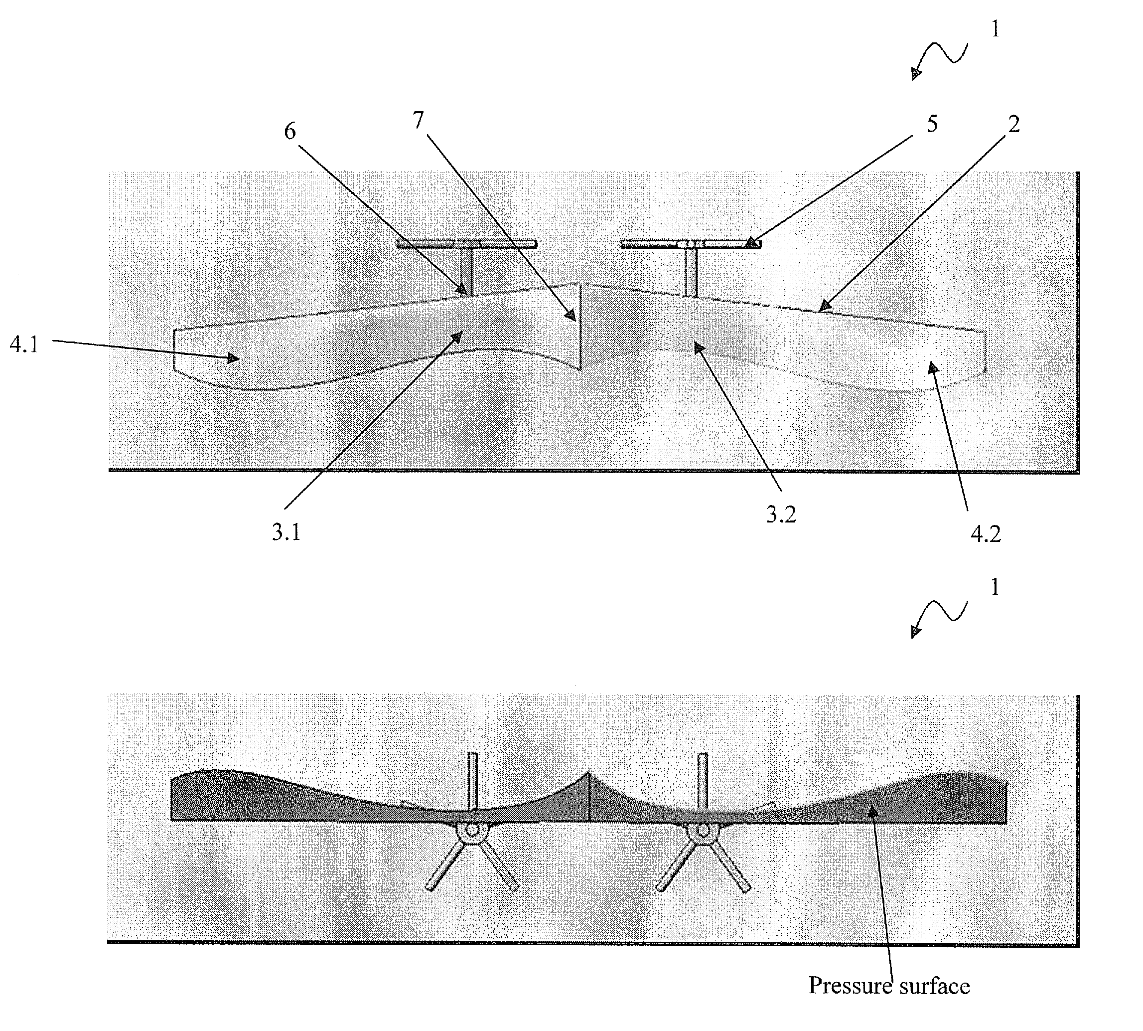
[0073]FIG. 7a illustrates top view of one embodiment of wing planform illustrating chord distribution according to present disclosure and FIG. 7b illustrates rear view of one embodiment of wing planform looking from the trailing edge of the aircraft according to present disclosure. The FIGS. 7a and 7b is an example of the optimized wing design obtained for a wing with a straight leading edge, a taper of 0.45 and a 3° linear washout. The constraints included CL=0.27, wing area, root chord, tip chord and bounds on twist (−14°≦αt≦14°). The optimized wing gives an induced drag reduction of 19.3% and a total drag reduction of 8.74%.

[0074]FIG. 8a illustrates top view of another embodiment of wing planform illustrating chord distribution according to present disclosure. FIG. 8b illustrates rear view of another embodiment of wing planform looking from the trailing edge of the aircraft according to present disclosure. The wing aspect ratio is about 12, the lifting coefficient (CL) is about 0...


PUM


Abstract

The disclosure relates to Aeronautics, more particularly relating to wing planforms that reduce wing drag substantially in aircraft driven by propellers or other rotors in tractor configuration. An aircraft comprising a wing and propeller system (1), said system comprising wing planform (2) characterized into wing chord regions (3) behind each propeller / rotor (5) whose length is relatively varied with respect to length of wing chord regions (4) at outboard of the propeller / rotor (5) towards wing tip and / or at inboard of the propeller (5) towards fuselage, and plurality of propellers (5) fixed ahead of wing leading edge such that induced drag is reduced by exploiting the velocity field generated by the slipstream of the propeller (5). Also, provides for a method of optimizing wing and propeller system and a method reducing induced drag, among other possible parameters of interest.

Description

CROSS-REFERENCE TO RELATED APPLICATIONS[0001]This application is a 371 U.S. National Stage of International Application No. PCT / IN2010 / 000448, filed Jul. 5, 2010, and claims priority to Indian patent application No. 01580 / CHE / 2009 filed Jul. 3, 2009, the disclosures of which are herein incorporated by reference in their entirety.TECHNICAL FIELD[0002]The disclosure relates to Aeronautics, more particularly relating to planforms that reduce wing drag substantially in aircraft driven by propellers or other rotors in tractor configuration.BACKGROUND[0003]The disclosure relates to the wing design for aircrafts driven by propellers or other rotors in tractor configuration and a method for reducing the induced drag and the total drag and / or any other such aerodynamic parameters of interest that is affected as a result of at least one propeller slipstream flowing onto a wing.[0004]In a propeller-driven aircraft there is an aerodynamic interaction between the propeller slipstream and the win...

Claims


Application Information

Patent Timeline
Patent Type & Authority Patents(United States)
IPC IPC(8): B64C3/00B64C39/10
CPCB64C3/00Y02T50/12B64C39/10Y02T50/10B64C3/10B64C11/46
Inventor NARASIMHA, RODDAMDESHPANDE, SURESH MADHUSUDANPRAVEEN, CHANDRASHEKARAPPARAKSHITH, BELUR RAGHAVAN
Owner JAWAHARLAL NEHRU CENT FOR ADVANCED SCI RES
Why Eureka
Try Eureka