Method and Engineering System for Modifying a Program of an Industrial Automation Component

a technology of industrial automation and engineering system, applied in the direction of electrical programme control, program control, instruments, etc., can solve the problems of complex programs, high risk of competing and uncoordinated modifications, and the program (control program) of modern industrial automation components

Active Publication Date: 2022-06-30
SIEMENS AG
View PDF8 Cites 0 Cited by
  • Summary
  • Abstract
  • Description
  • Claims
  • Application Information

AI Technical Summary

Problems solved by technology

The programs (control programs) for modern industrial automation components (programmable logic controller (PLC)) are highly complex and therefore consist of a multiplicity of program elements.
The programs are so complex that multiple program developers at multiple workstations, i.e., with multiple engineering systems, often work on a project simultaneously.
Problems can arise in particular if multiple workers work on the program of one and the same industrial automation component (PLC) simultaneously, because the risk of competing and uncoordinated modifications is then particularly high.
In particular, modifications to the interfaces of program elements often lead to inconsistent states of the controller or of automation components.
In such a case, the controller can be put into the “stop” state without this being foreseeable, and can then even cause damage to a process-engineering installation or a production installation.
As such, there are strategies that do not actually prevent a user from producing an inconsistent state on the automation component.
Although this often prevents further damage, there is naturally a production downtime as a result of the control device (automation component) having been taken out of operation.
Although this largely prevents sudden shutdowns and therefore improves runtime performance, it leads to restrictions on the use of the engineering systems because the frequent synchronization and the associated upload of software is complex and the performance of the engineering, of the automation component and of the network is adversely affected.
In short, the strategy just outlined shifts the problem of synchronization from the execution environment of the automation component to the engineering systems, but does not improve it overall.

Method used


Image

  • Method and Engineering System for Modifying a Program of an Industrial Automation Component
  • Method and Engineering System for Modifying a Program of an Industrial Automation Component

Examples


Embodiment Construction

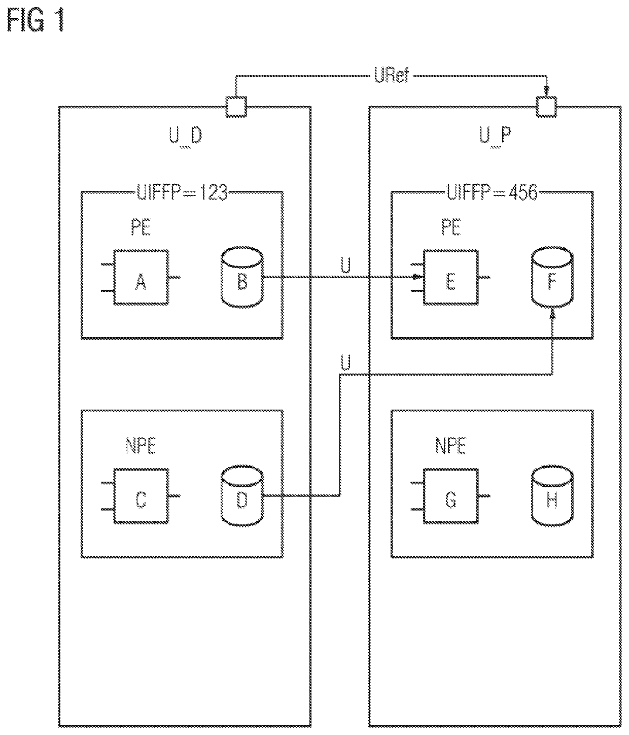
[0034]FIG. 1 shows two units U_D, U_P, for example, the unit U_D for a drilling operation (drill) and the unit U_P for a specific method step (process).

[0035]The unit U_D references the unit U_P, this being symbolized by the arrow with the reference sign URef. Various program elements A, . . . , H are arranged in the units U_D, U_P, where the program elements A, B, E, F are published program elements (public elements (PE)) and the program elements C, D, G, H are unpublished program elements (non-public elements (NPE)). The program elements PE published by the units U_P and U_D are also referenceable, i.e., usable or addressable, by program elements that do not belong to the individual unit. Unpublished program elements NPE are usable or referenceable only within the same unit. The term “relation” is sometimes also used instead of “reference” for the relationship between modules that are in a use relationship. In general, the program elements can be executable program code, such as p...


PUM


Abstract

A method for modifying a program of an industrial automation component, wherein the program includes a plurality of program elements, where the program is structured in units, a unit includes a group of program elements and can include both published program elements having an interface that can be referenced by the program elements of other units and unpublished program elements, and where a checksum is calculated and is assigned to the unit using the interfaces, such that if at least one program element of the version of the unit stored in the engineering system is modified, then the modified checksum is compared with the previous checksum version present in the automation component, and only the modified unit is transferred if the checksums match such that consistency of the program is maintained and the software updateable more quickly.

Description

CROSS-REFERENCE TO RELATED APPLICATIONS[0001]This is a U.S. national stage of application No. PCT / EP2020 / 061137 filed 22 Apr. 2020. Priority is claimed on European Application No. 19175904.2 filed 22 May 2019, the content of which is incorporated herein by reference in its entirety.BACKGROUND OF THE INVENTION1. Field of the Invention[0002]The invention relates to a method for modifying a program of an industrial automation component and to an engineering system for modifying the program of the industrial automation component.2. Description of the Related Art[0003]Industrial automation components, in particular programmable logic controllers, are used for automating production systems and for automating process-engineering installations. This regularly involves sensor values being processed by a running program and converted into commands for actuators, as a result of which a control task can be performed.[0004]The programs (control programs) for modern industrial automation componen...

Claims


Application Information

Patent Timeline
Patent Type & Authority Applications(United States)
IPC IPC(8): G05B19/418
CPCG05B19/41835G05B19/41845G05B2219/23199G05B2219/25235G05B2219/25157G06F8/658G05B19/0426G05B19/056G06F9/44552G05B2219/33003G06F8/65
Inventor FISCHER, CHRISTIANFRANK, MICHAELPFAHLMANN, LOTHAR
Owner SIEMENS AG
Why Eureka
Try Eureka