Reflective film combinations with output confinement in both polar and azimuthal directions and related constructions

a technology of polar and azimuthal directions and output confinement, applied in the field of optical films, to achieve the effects of reducing glare, broadening the angular distribution of output light, and improving spatial uniformity

Inactive Publication Date: 2014-12-23
3M INNOVATIVE PROPERTIES CO
View PDF65 Cites 12 Cited by
  • Summary
  • Abstract
  • Description
  • Claims
  • Application Information

AI Technical Summary

Benefits of technology

[0009]Surprisingly, we have found that the angular width or degree of collimation of the oblique transmission lobe in the azimuthal direction can depend strongly on the orientation of the multilayer optical film relative to the polarizer. In particular, the choice of which of the two opposed major surfaces of the multilayer optical film faces the polarizer can have a dramatic effect on the degree of collimation of the oblique transmission lobe in the azimuthal direction. We have found this to be the case where the multilayer optical film contains a plurality of microlayers arranged into optical repeat units for reflecting light over an extended wavelength band, and where the optical repeat units have an optical thickness distribution across a thickness of the multilayer optical film such that thinner ones of the optical repeat units are disposed generally towards one major surface (a “thin side”) of the multilayer film and thicker ones of the optical repeat units are disposed generally towards the other major surface (a “thick side”) of the multilayer optical film. Such a layer thickness arrangement may occur, for example, if the optical repeat units are arranged to have a monotonically increasing or monotonically decreasing thickness gradient across the thickness of the film. In some cases the orientation of the polarizer with respect to the multilayer optical film can also have an effect on the azimuthal collimation of the oblique transmission lobe.
[0012]The off-axis transmission lobe or light leakage makes the combination suitable for use in direct-lit backlights and similar lighting systems in which the combination can be placed in front of the lamp(s), with or without other intermediate optical films or bodies, in order to help disperse light emitted by the lamp(s) for better spatial uniformity and to help hide or obscure the lamp(s). The combination can also be used in general illumination systems such as luminaires and task lighting to provide a balance of on-axis and off-axis illumination to help broaden the angular distribution of the output light for reduced glare or other desired design objectives. Prismatic films and similar light management films can also be included to redirect highly oblique light exiting the multilayer optical film towards the viewing axis of the system or in other directions as desired.
[0013]Because of the asymmetric nature of the light leakage, and the limited range of azimuthal angles associated with the transmission lobes, the combination is well suited for use with linear light sources, i.e., a light source that extends physically along a light source axis and is much shorter or confined along other axes perpendicular to the light source axis. A straight tubular fluorescent bulb is one example of such a source, and a plurality of individual LEDs arranged in a line is another example. The combination can be beneficially oriented such that the first or weak plane of incidence, along which the transmission lobes are aligned, is substantially perpendicular to the light source axis. The first plane of incidence can alternatively be aligned parallel to the light source axis. In this alternative configuration, much of the light undergoes multiple reflections in order to be redirected to exit along the weak axis, resulting in a more uniform mixing of the light before exiting through the combination. A low absorption system is important in this case so as to maintain a high efficiency system.
[0014]The disclosed reflective multilayer optical films—as well as exemplary polarizers for use in combination with such films—can be made to have low absorption losses in the visible region or other wavelength region of interest, so that nearly all such light that is not transmitted by the film is reflected by the film, and vice versa, or Rhemi+Themi≈100%, where Rhemi refers to the total hemispherical averaged reflectivity of the film, and Themi refers to the total hemispherical averaged transmissivity of the film. As such, the disclosed combinations can advantageously be used in lighting systems that employ light recycling. A disclosed combination may for example be placed in a direct-lit system with a back reflector and one or more lamps disposed between the back reflector and the film. Light that is not initially transmitted by the combination can be reflected by the back reflector back towards the combination for another opportunity to be transmitted.

Problems solved by technology

At certain oblique angles, however, these same films become highly transmissive for p-polarized light over the extended wavelength range.

Method used


Image

  • Reflective film combinations with output confinement in both polar and azimuthal directions and related constructions
  • Reflective film combinations with output confinement in both polar and azimuthal directions and related constructions
  • Reflective film combinations with output confinement in both polar and azimuthal directions and related constructions

Examples


Embodiment Construction

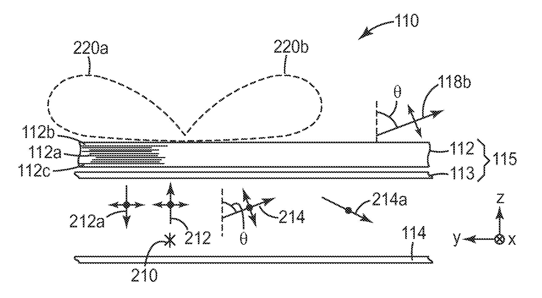
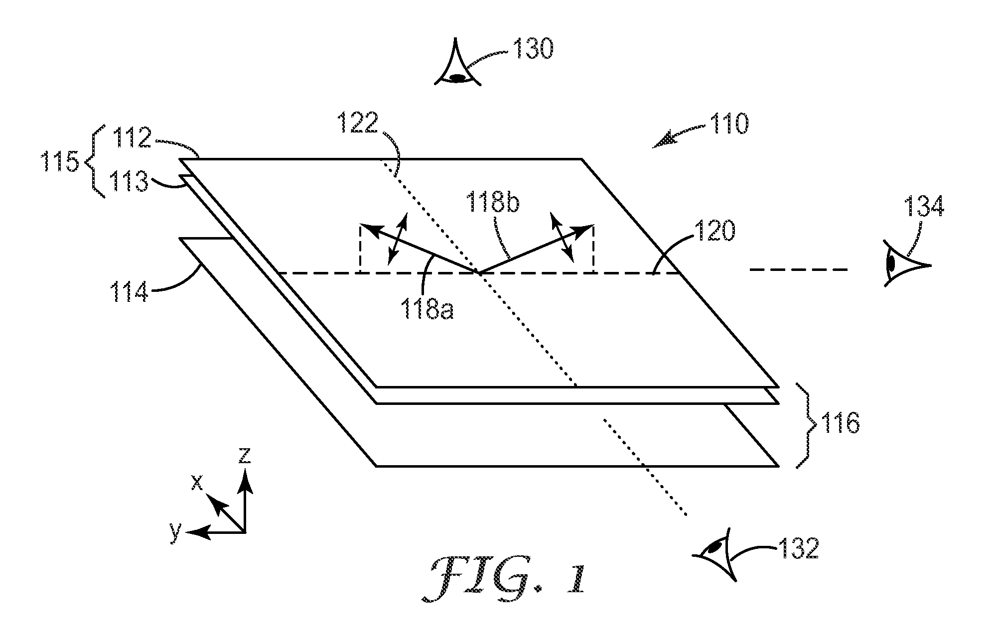
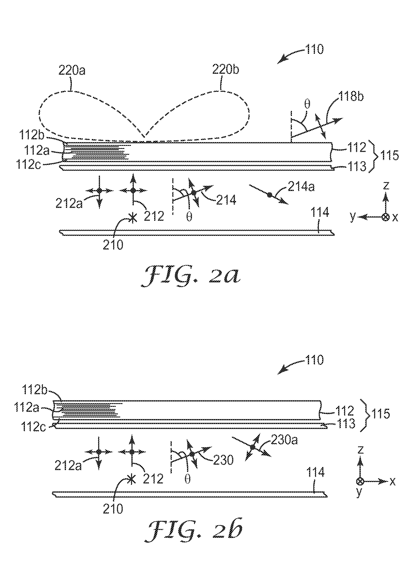
[0056]FIG. 1 depicts a simplified perspective view of a lighting system 110 that utilizes a reflective multilayer optical film 112 in combination with a polarizer 113, the combination of these elements being assigned reference numeral 115 and having a batwing transmission characteristic. The system 110 also includes a high reflectivity back reflector 114 which is substantially coextensive with and opposed to combination 115 so as to form a light recycling cavity 116 therebetween. Thus, light reflected by the combination 115 can be reflected again by back reflector 114 towards the combination 115 for another opportunity to be transmitted for improved system efficiency and reduced losses.

[0057]The film 112 and polarizer 113 are shown as separate films spaced apart slightly from each other for ease of illustration. In practice, these components may be so separated if desired, or they may be attached to each other e.g. by lamination or through one or more intermediate optical films or b...


PUM

PropertyMeasurementUnit
reflectivity R2aaaaaaaaaa
incidence angleaaaaaaaaaa

Abstract

A reflective film includes microlayers arranged into optical repeat units to reflect light in an extended wavelength band, with thinner and thicker ones of the optical repeat units being disposed generally towards a thin side and thick side, respectively, of the film. The microlayers are tailored to provide the film with a reflectivity, for p-polarized light incident in a first plane, that decreases by at least half from an initial value at normal incidence to a value R1 at an incidence angle θoblique. The film has a reflectivity for p-polarized light incident in a second plane of R2 at the angle θoblique, where R2>R1. A polarizer is combined with the reflective film, the combination defining an oblique transmission lobe, and the thick and thin sides of the reflective film are oriented relative to the polarizer to reduce an azimuthal width Δφ of the transmission lobe.

Description

CROSS REFERENCE TO RELATED APPLICATIONS[0001]This application is a national stage filing under 35 U.S.C. 371 of PCT / US2009 / 064628, filed on Nov. 16, 2009, which claims priority to U.S. Provisional Application No. 61 / 116,294, filed on Nov. 19, 2008, the disclosure of which is incorporated by reference in its / their entirety herein.FIELD OF THE INVENTION[0002]This invention relates generally to optical films, with particular application to such films whose reflection characteristics are determined in large part by constructive and destructive interference of light reflected from interfaces between microlayers within the film. The invention also relates to associated systems and methods.BACKGROUND[0003]Multilayer optical films, whose reflection and transmission characteristics are based exclusively or predominantly on constructive and destructive interference of light reflected from interfaces between a plurality or stack of optically thin layers (“microlayers”) within the film, are kno...

Claims


Application Information

Patent Timeline
Patent Type & Authority Patents(United States)
IPC IPC(8): G02F1/1335G02B5/30F21V8/00G02B5/08
CPCG02F1/133615G02B6/0053G02F2001/133545G02B5/305G02F1/133617G02B6/0056G02F2001/133607G02B5/3083G02F1/13362G02B5/0841G02F2202/40G02B5/3066G02F1/133606G02B6/0051G02F2203/06G02F1/133611G02F1/133545G02F1/133607B32B7/00G02B5/02G02B5/08G02B5/30
Inventor WEBER, MICHAEL F.BENOIT, GILLES J.
Owner 3M INNOVATIVE PROPERTIES CO
Why Eureka
Try Eureka