Methods and apparatus for dynamic automated configuration within a control plane of a switch fabric

a technology of control plane and switch fabric, which is applied in the direction of data switching network, instruments, digital transmission, etc., can solve the problems of large potentially unmanageable, and complex and time-consuming tasks for administrator, and achieves the effect of reducing the number of cables used in the system and reducing the number of cables used

Active Publication Date: 2014-12-23
JUMIPER NETWORKS INC
View PDF101 Cites 107 Cited by
  • Summary
  • Abstract
  • Description
  • Claims
  • Application Information

AI Technical Summary

Benefits of technology

[0006]In one embodiment, a method includes receiving a first identifier and a private key after a network device has been included in a data center switch fabric control plane, authenticating the network device based on the private key, sending a second identifier to the network device, and sending a

Problems solved by technology

Thus, the number of cables used in the system can be relatively large and potentially unmanageable.
Additionally, provisioning the modules, network devices, and storage devices can be a complex and ti

Method used


Image

  • Methods and apparatus for dynamic automated configuration within a control plane of a switch fabric
  • Methods and apparatus for dynamic automated configuration within a control plane of a switch fabric
  • Methods and apparatus for dynamic automated configuration within a control plane of a switch fabric

Examples


Embodiment Construction

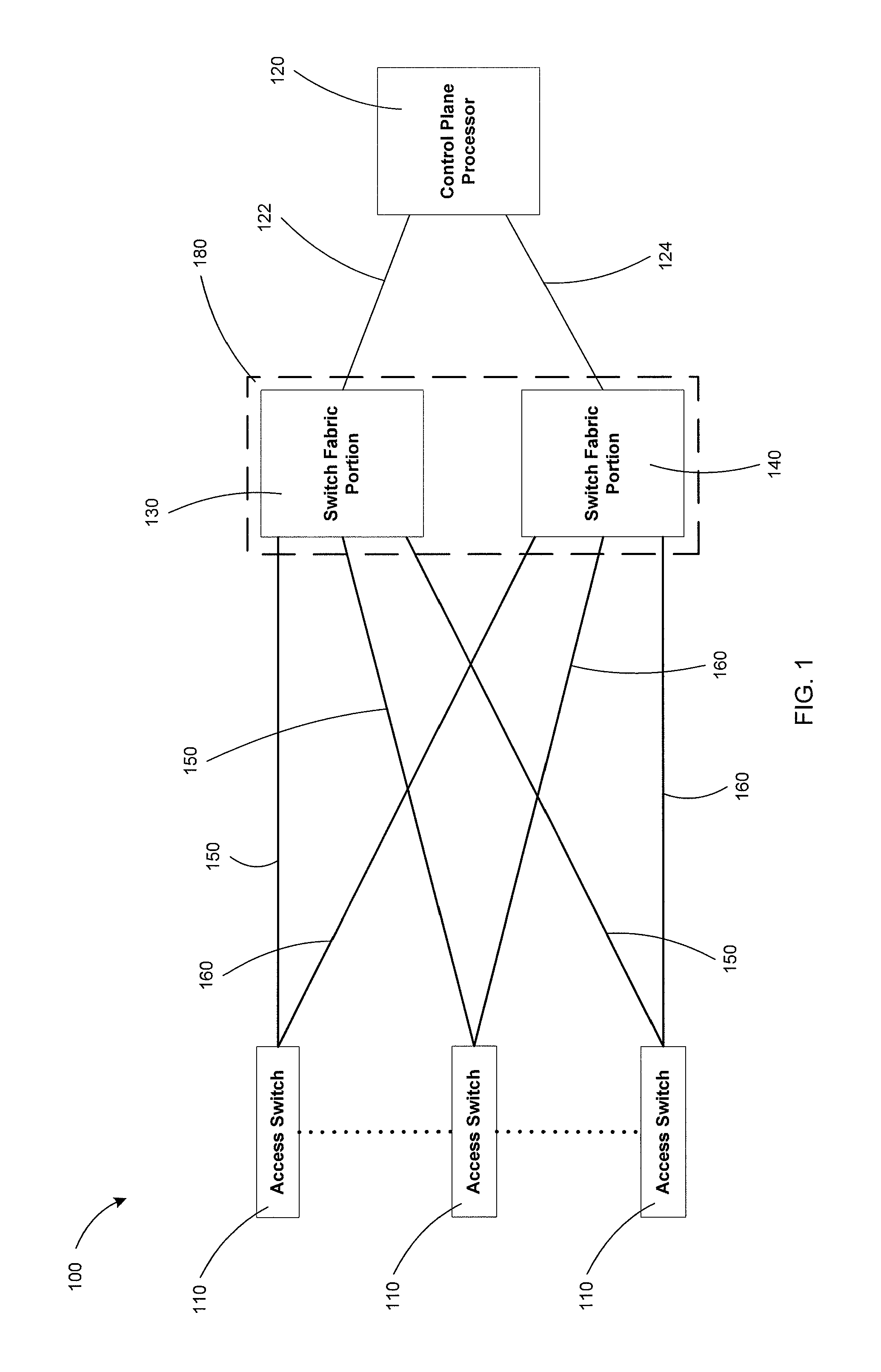
[0015]In some embodiments, a system includes multiple access switches, a switch fabric having multiple switch fabric portions, and a control plane processor. Each switch fabric portion is coupled to at least one access switch by a cable from a first set of cables. Each switch fabric portion is configured to receive data from the at least one access switch via the cable from the first set of cables. The control plane processor is coupled to each switch fabric portion by a cable from a second set of cables. The control plane processor is configured to send control information to each access switch via a cable from the second set of cables, a switch fabric portion, and a cable from the first set of cables. Because each cable from the first set of cables can carry both data signals and control signals (i.e., each cable from the first set of cables includes a portion of the data plane of the system and a portion of the control plane of the system, as described in further detail below), i...


PUM


Abstract

In one embodiment, a method includes receiving a first identifier and a private key after a network device has been included in a data center switch fabric control plane, authenticating the network device based on the private key, sending a second identifier to the network device, and sending a control signal to the network device based on the second identifier. The first identifier is associated with the network device and unique within a segment of the data center switch fabric control plane. The second identifier is unique within the segment of the data center switch fabric control plane.

Description

BACKGROUND[0001]Embodiments described herein relate generally to methods and apparatus for configuring devices within a control plane of a switch fabric. Some embodiments relate more specifically to dynamic automated configuration of network devices within a control plane of a switch fabric.[0002]Switch fabrics can be used, for example, to route data between multiple network devices and / or storage devices. Each network device and / or storage device can be operatively coupled to the switch fabric and can control data input to and output from the switch fabric. In this manner, each network device and / or storage device can send data to the switch fabric and receive data from the switch fabric.[0003]Control processors can be used to monitor and / or control the operation of the switch fabric. For example, a control processor can be used to maintain and / or distribute a routing table to modules within the various stages of the switch fabric and / or the network devices and / or storage devices c...

Claims


Application Information

Patent Timeline
IPC IPC(8): H04L29/08H04L12/715H04L12/46
CPCH04L12/4641H04L45/04H04L63/0272H04L63/0823H04L63/00H04L63/02H04L63/061H04L63/0876H04L2101/622H04L41/0806H04L63/06H04L63/08
Inventor KUMAR, JAINENDRADIXIT, VINEETSESHACHELLUM, PRABHU
Owner JUMIPER NETWORKS INC
Why Eureka
Try Eureka