Rolling element bearing

a technology of rolling element and bearing, which is applied in the direction of roller bearings, sliding contact bearings, mechanical equipment, etc., can solve the problems of raceway corrosion, damage to the raceway of the outer ring, and risk, so as to prevent early failure, prevent scrapping, and prolong the service life

Inactive Publication Date: 2014-12-30
AB SKF
View PDF36 Cites 0 Cited by
  • Summary
  • Abstract
  • Description
  • Claims
  • Application Information

AI Technical Summary

Benefits of technology

[0022]With the proposed conception of a rolling-element bearing, a substantial prevention of corrosion on the outer ring raceway and the rolling elements is possible, in particular in the case of double row barrel roller bearings (spherical roller bearings) and self-aligning ball bearings, wherein condensation formation can occur (e.g. in paper machines), and also there where bearings can be damaged by washing liquids.
[0023]The bearing service life can be substantially extended by the proposed design. Furthermore, early failures can be prevented.
[0024]Corrosion can make the bearing irreparable; the proposed condensation- or liquid-collecting groove thus makes it possible to maintain the bearing in a better condition, so that in the given case repairs are still possible and scrapping can be prevented. Only the condensation-collecting groove will corrode, however not the adjacent raceways for the rolling elements.

Problems solved by technology

Accordingly the risk exists that even with relatively little moisture the raceways can corrode.
Up to this point, however, damage to the raceways of the outer ring has sometimes already occurred.
The condensation of moisture in the bearing accordingly leads to an idle-state-corrosion of the raceways, which negatively affects the raceways, i.e. the functional surfaces of the bearing, even with relatively small amounts of liquid.
In this way, bearing failures due to corrosion are caused relatively quickly in a disadvantageous manner.
The bearings also quickly become incapable of being repaired, i.e. with sufficient corrosion a repair is no longer possible; instead the bearing must be scrapped.

Method used


Image

  • Rolling element bearing
  • Rolling element bearing
  • Rolling element bearing

Examples


Embodiment Construction

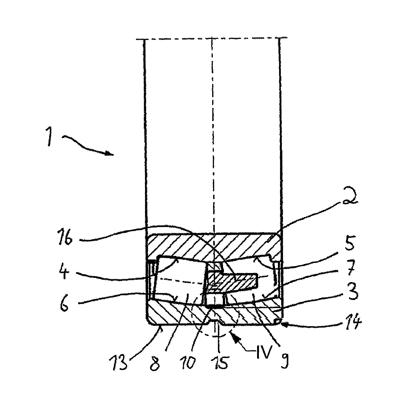
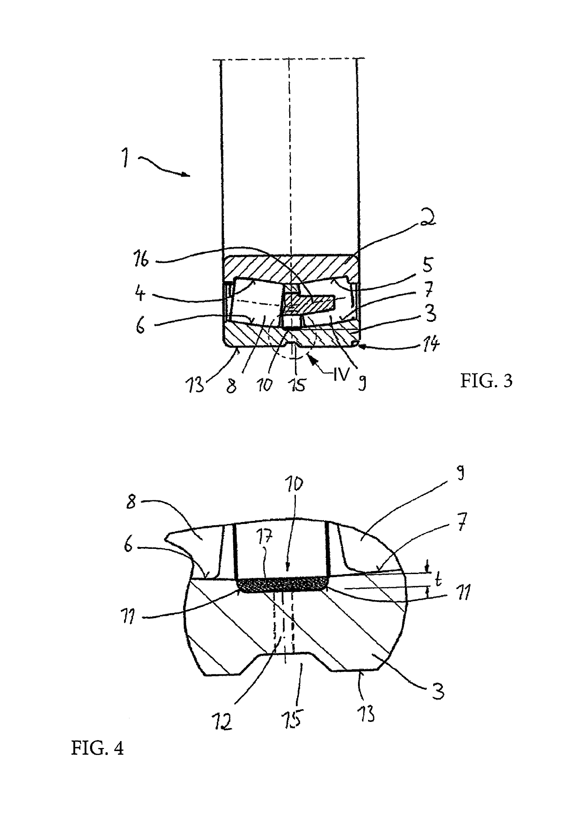
[0031]An inventively-designed spherical roller bearing 1 is shown in FIG. 3. The inner ring2 and the outer ring 3 have—as was explained in connection with FIG. 1—respective raceways 4 and 5 or 6 and 7 for the rolling element rows 8 and 9.

[0032]The outer ring raceways 6 and 7 now however are not produced as sections of a continuous spherical shape of the radially-inner-lying surface of the outer ring 3. Rather, a groove 10 in the form of a circulating annular groove is machined between the two raceways 6 and 7.

[0033]As can be seen in the detailed view in FIG. 4, the groove 10 has a substantially rectangular shape in radial section. The axial end regions of the groove 10 are only provided with roundings 11.

[0034]The groove depth t is chosen such that—without appreciably weakening the outer ring 3—a sufficient holding space for liquid is formed in the region of the deepest point of the outer ring 3. The maximum possible fluid level of the liquid can thus reach the groove depth t before...


PUM


Abstract

A rolling-element bearing includes an inner ring and an outer ring having at least two adjacently disposed raceways for at least two rows of rolling elements. In order to avoid or reduce corrosion on the raceways of the outer ring caused by condensation forming on the outer raceway, the outer ring has at least one radially-outwardly-extending groove in the axial region between its at least two raceways for collecting condensation at a location away from the raceways.

Description

CROSS-REFERENCE[0001]This application is the U.S National Stage of International Application No. PCT / EP2012 / 051736 filed on Feb. 2, 2012, which claims priority to German patent application no. 10 2011 003 513.3 filed on Feb. 2, 2011.Technical Field[0002]The invention relates to a rolling-element bearing, comprising an inner ring and an outer ring, wherein the inner ring and the outer ring have at least two raceways disposed adjacent to one another for at least two rows of rolling elements.BACKGROUND[0003]Rolling-element bearings of this type come into use for example in paper-making machines and in this case are often embodied as spherical roller bearings. These bearings have the advantage that (small) pivoting angles between the axes of the inner ring and of the outer ring can be compensated. The outer ring raceway in this case extends arcuately, wherein respective sections of the arc function as raceways.[0004]In the mentioned usage—but of course also in other usages—the bearing m...

Claims


Application Information

Patent Timeline
Patent Type & Authority Patents(United States)
IPC IPC(8): F16C19/06F16C19/38F16C19/08F16C23/08F16C33/58F16C33/66F16C41/00D21G1/02D21F7/02F16C19/52F16C33/46
CPCF16C19/52F16C41/008D21F7/02F16C19/08F16C33/4605F16C19/06F16C33/6681F16C33/583D21G1/0226F16C33/6629F16C23/086F16C33/585F16C19/38
Inventor BRAMESHUBER, JOSEFKOETTRITSCH, HUBERT FRIEDRICHSTROHMAYR, GERHARD
Owner AB SKF
Why Eureka
Try Eureka