
Picture in picture clip applier video system

a video system and clip technology, applied in the field of endoscopic video systems, can solve the problems of affecting the accuracy of surgeons using the endoscopic video system and the endoscopic tool to accurately determine the position of the endoscopic, affecting the surgeon's ability to properly position the clip relative, and damage the clip applier and the clip, so as to enhance the accuracy and safety of the medical procedure, prevent damage to the endoscopic video system and the accompanying endoscopic, and enhance the multi-angle view of the cavity

Active Publication Date: 2014-12-30
MICROLINE SURGICAL INC
View PDF77 Cites 1 Cited by
  • Summary
  • Abstract
  • Description
  • Claims
  • Application Information

AI Technical Summary

Benefits of technology

The present invention provides an endoscopic video system with multiple imaging systems for enhanced viewing during medical procedures, improving accuracy and safety, and preventing damage to the system and patient. The system includes a non-limiting optical fiber design that reduces stress when rotating with the tool. The clip applier includes a bearing that prevents twisting of the optical fiber and a service loop to reduce stress on the fiber when rotating with the tool. Overall, the invention improves the viewing capabilities of endoscopy and ensures the well-being of the patient and medical team during procedures.

Problems solved by technology

A problem exists that it is difficult for a surgeon using the endoscopic video system and the endoscopic tool to accurately determine a position of the endoscopic tool relative to objects provided in the viewable cavity.
For example, if the endoscopic tool were configured as a clip applier, and the surgeon were placing clips around an artery along the length of the artery at spaced intervals, the lack of visibility (at the site of the clip placement) hinders the ability of the surgeon to properly position a clip relative to a previously positioned clip.
In fact, a surgeon viewing the video monitor to observe the movements of the clip applier in the cavity may accidentally place a clip too far from or too close to the previously positioned clip, or the surgeon may even accidentally cause the clip to overlap the previously positioned clip.
Such accidental placement of the clip may damage the clip applier and the clips, and may even cause injury to the patient.

Method used


Image

  • Picture in picture clip applier video system
  • Picture in picture clip applier video system
  • Picture in picture clip applier video system

Examples


Embodiment Construction

[0045]The particulars shown herein are by way of example and for purposes of illustrative discussion of the embodiments of the present invention only and are presented in the cause of providing what is believed to be the most useful and readily understood description of the principles and conceptual aspects of the present invention. In this regard, no attempt is made to show structural details of the present invention in more detail than is necessary for the fundamental understanding of the present invention, the description taken with the drawings making apparent to those skilled in the art how the several forms of the present invention may be embodied in practice.

[0046]Accordingly, the present disclosure relates to an endoscopic video system for visualizing an internal body cavity, including an endoscopic instrument, such as a clip applier, capable of being incorporated into the endoscopic video system. However, it is contemplated that other known endoscopic instruments may also b...


PUM


Abstract

An endoscopic video system for visualizing an internal body cavity is provided. The endoscopic video system may include a first instrument and a second instrument. The first instrument may include a light configured to illuminate the cavity, and a first camera configured to capture first images of the illuminated cavity. The second instrument may include a surgical tool configured to perform a surgical procedure, and a second camera configured to capture second images of the illuminated cavity. In addition, the endoscopic video system may further include a video control unit configured to receive the captured first and second images, and a video display configured to display the captured first and second images transmitted from the video control unit.

Description

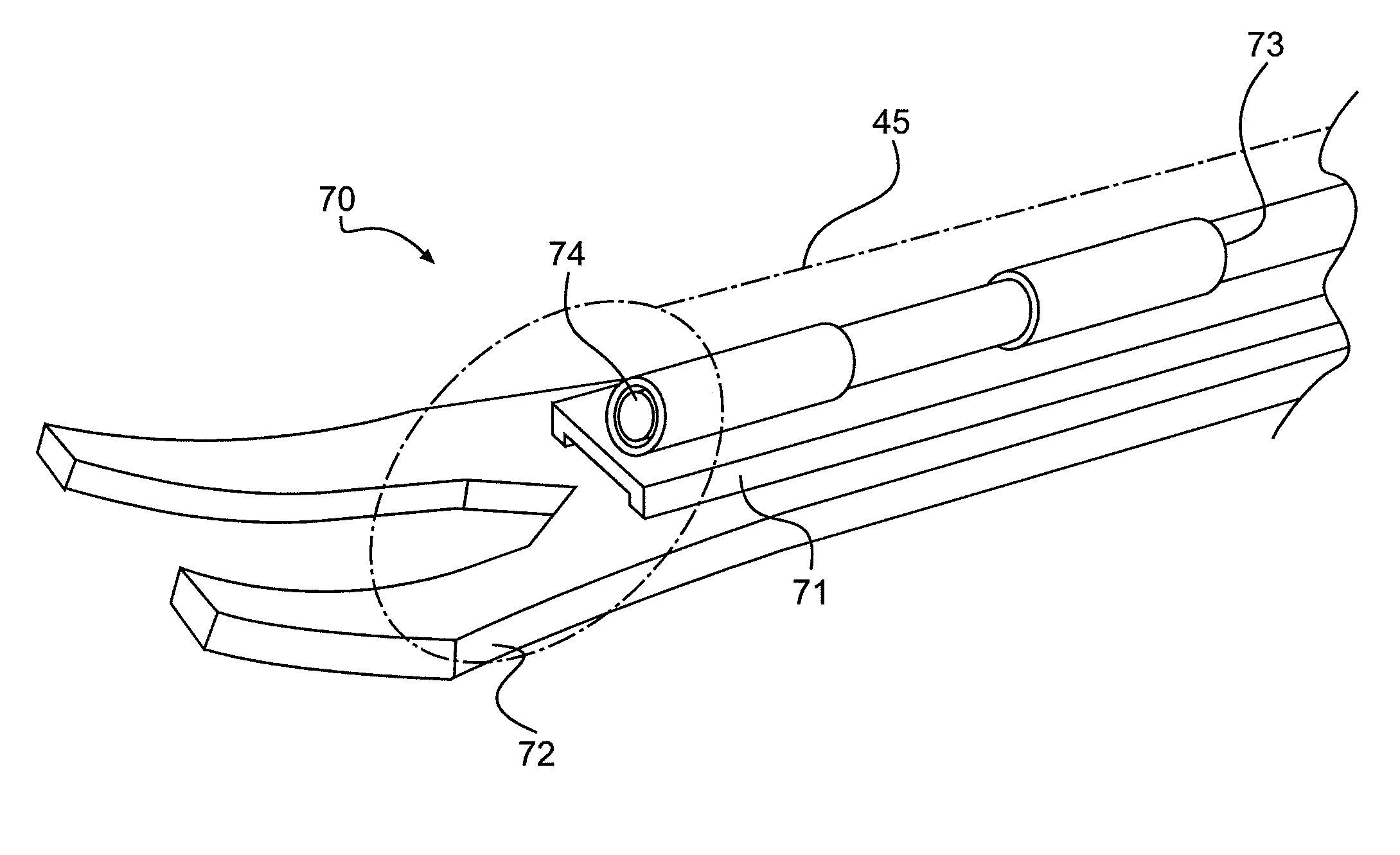
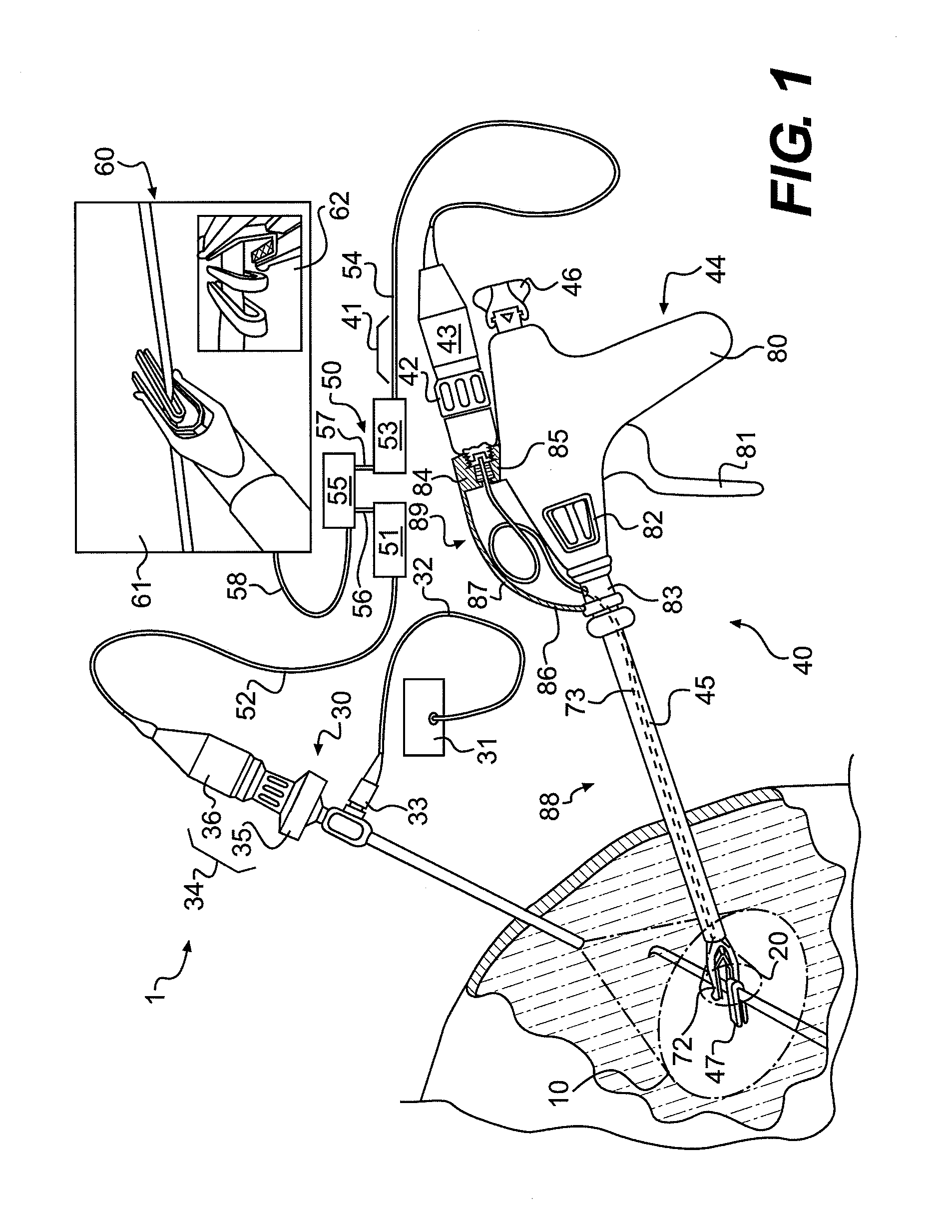
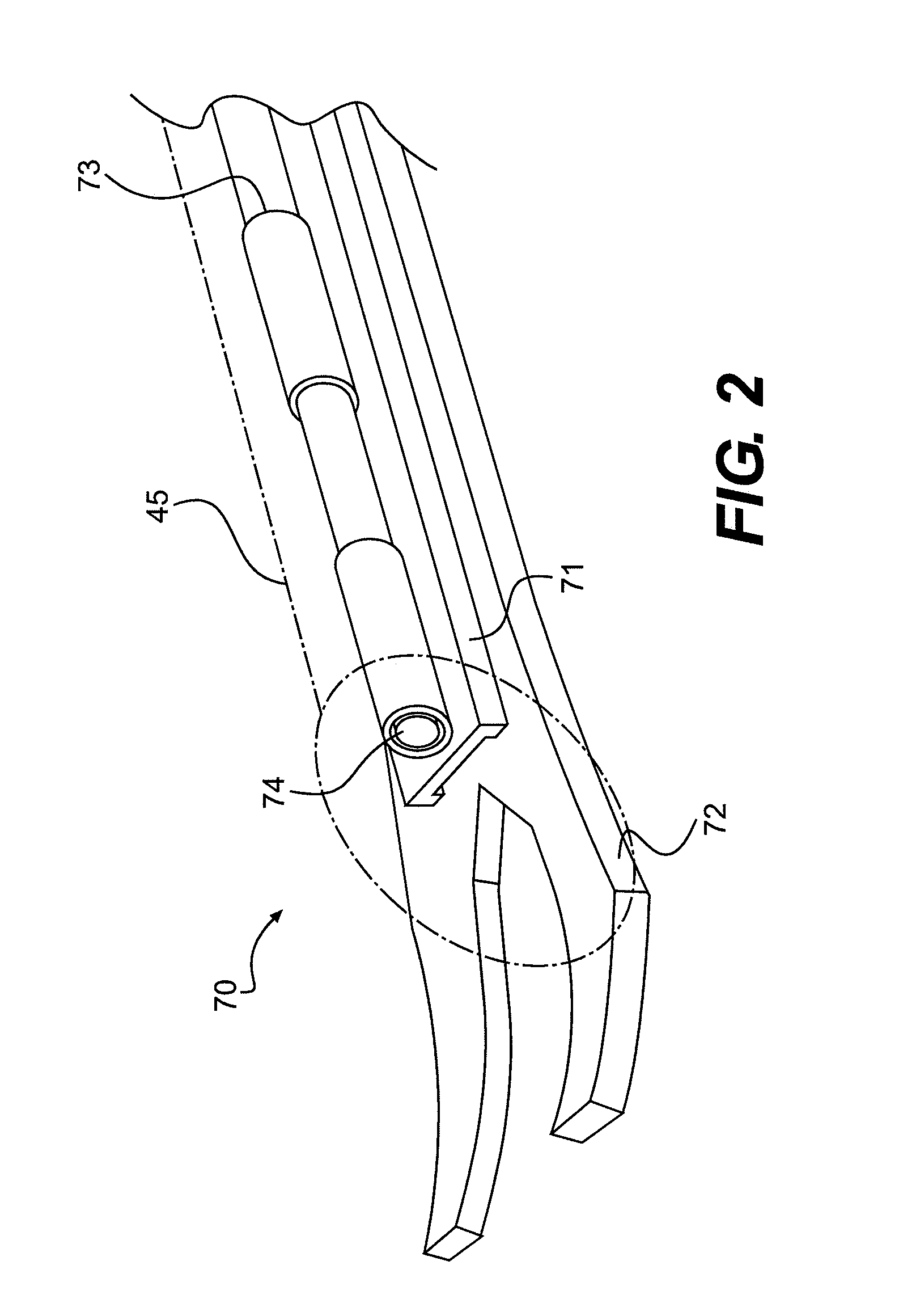
BACKGROUND OF THE INVENTION[0001]1. Field of the Invention[0002]This disclosure relates to an endoscopic video system with picture-in-picture capabilities and an endoscope for use in the endoscopic video system.[0003]2. Description of the Related Art[0004]Traditional endoscopic video systems generally include an endoscope having an objective lens system provided at a distal end of the endoscope that forms an image that can be seen on, for example, a video monitor. In medical applications, the endoscopic video systems are utilized to view images within a closed cavity of a patient. Often these endoscopic video systems can be used in conjunction with various sorts of endoscopic tools to perform a medical procedure. One such tool is a clip applier, which may utilize a clip to grasp and / or crimp / seal tissue by the single hand of an operating surgeon, and is described in commonly-assigned U.S. Patent Publication No. 2003 / 0040759, U.S. Patent Publication 2007 / 0049950 and U.S. Pat. No. 6,2...

Claims


Application Information

Patent Timeline
Patent Type & Authority Patents(United States)
IPC IPC(8): A61B19/00A61B1/05A61B1/00H04N5/45A61B17/128A61B1/313
CPCA61B1/05A61B1/3132A61B2019/5206A61B17/1285A61B19/5212H04N5/45A61B90/361A61B2090/306
Inventor BOULNOIS, JEAN-LUCDEVLIN, CHRISTOPHER
Owner MICROLINE SURGICAL INC
Learn More