Multi-phase clock switching device and method thereof
a switching device and multi-phase technology, applied in the direction of digital transmission, electrical equipment, angle demodulation by phase difference detection, etc., can solve problems such as circuits using this clock, and achieve the effect of enhancing signal quality and accuracy
- Summary
- Abstract
- Description
- Claims
- Application Information
AI Technical Summary
Benefits of technology
Problems solved by technology
Method used
Image
Examples
Embodiment Construction
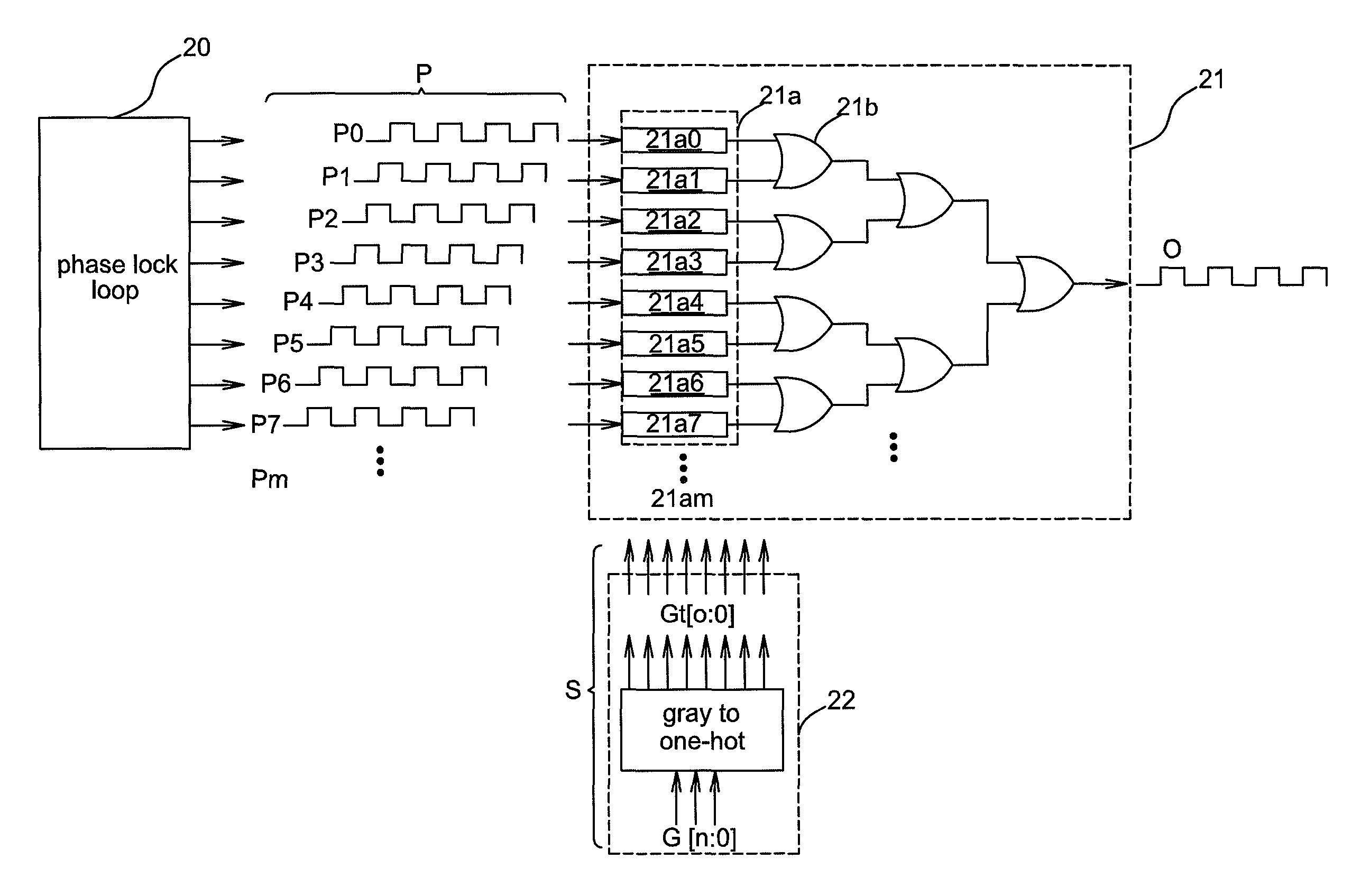
[0037]FIG. 2A shows a schematic diagram illustrating an embodiment of a multi-phase clock switching device 21 and peripheral devices thereof. In the figure, a phase lock loop 20, a multi-phase clock switching device 21, and a signal generator 22 are shown. The multi-phase clock switching device 21 receives a plurality of phase clock signals P (P0˜Pm where m is a positive integer less than infinity) generated by the phase lock loop 20 and determines how to output the phase clock signals P to generate an output clock signal O according to a switching signal S generated by the signal generator 22.
[0038]In an embodiment, the signal generator 22 may be a code conversion unit, such as a gray to one-hot conversion unit in the figure that converts the gray code G[n:0] into a binary code Gt[o:0] to generate a switching signal S with a binary code. For example, G[2:0] may be converted into Gt[7:0]. In the above, “n” and “o” are integers less than infinity and then =o=nm−1, where m is an integ...
PUM
 Abstract
Description
Claims
Application Information
 - R&D
- Intellectual Property
- Life Sciences
- Materials
- Tech Scout
- Unparalleled Data Quality
- Higher Quality Content
- 60% Fewer Hallucinations
Browse by: Latest US Patents, China's latest patents, Technical Efficacy Thesaurus, Application Domain, Technology Topic, Popular Technical Reports.
© 2025 PatSnap. All rights reserved.Legal|Privacy policy|Modern Slavery Act Transparency Statement|Sitemap|About US| Contact US: help@patsnap.com


