Method for producing a shell catalyst and corresponding shell catalyst

a shell catalyst and catalyst technology, applied in the direction of physical/chemical process catalysts, metal/metal-oxide/metal-hydroxide catalysts, cell components, etc., can solve the problems of product selectivity and catalyst activity adverse effects, and achieve the effect of uniform concentration of catalytically active species and uniform shell thickness

Active Publication Date: 2015-01-06
CLARIANT INT LTD
View PDF194 Cites 3 Cited by
  • Summary
  • Abstract
  • Description
  • Claims
  • Application Information

AI Technical Summary

Benefits of technology

[0009]It is therefore an object of the present invention to provide a shell catalyst production method by means of which it is possible to produce shell catalysts which, over comparatively large regions of their shell thickness, have a substantially uniform concentration of catalytically active species and a substantially uniform shell thickness.

Problems solved by technology

However, this technique has reached its limits as far as the minimum shell thicknesses and maximum Au loading are concerned.
Furthermore, the catalysts produced by means of impregnation have nonuniform shell thicknesses and a very nonuniform concentration of catalytically active species over comparatively large regions of their shell thickness, which can have an adverse effect on the product selectivity and on the activity of the catalyst.

Method used


Image

  • Method for producing a shell catalyst and corresponding shell catalyst
  • Method for producing a shell catalyst and corresponding shell catalyst
  • Method for producing a shell catalyst and corresponding shell catalyst

Examples


Embodiment Construction

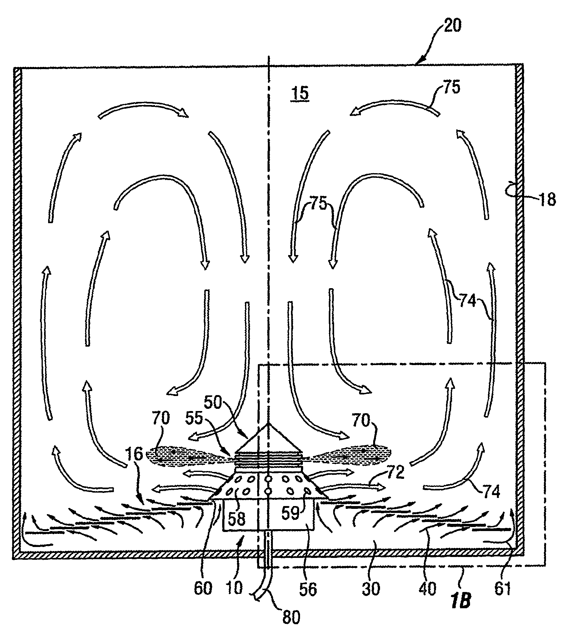
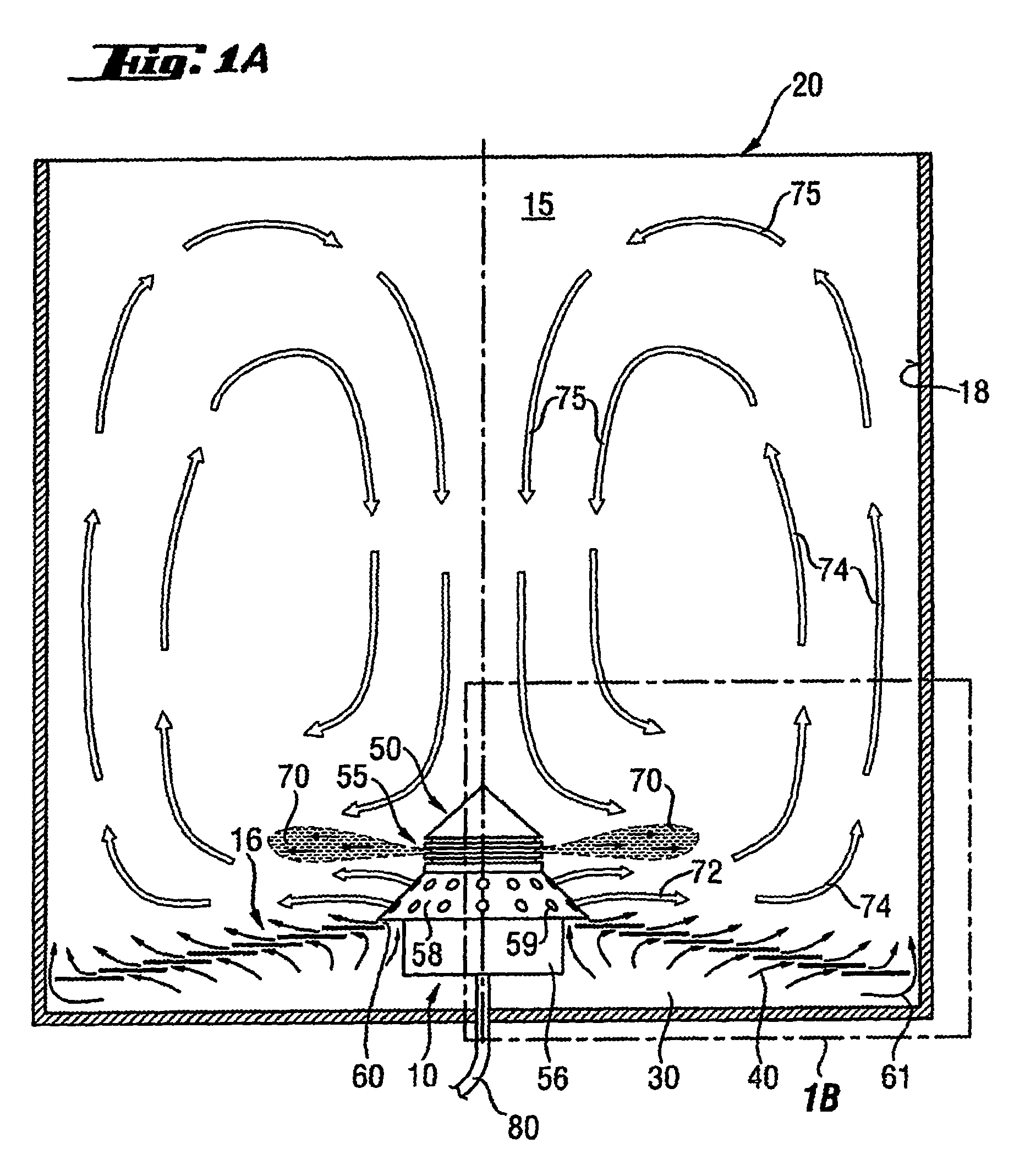
[0188]FIG. 1A shows an device given the reference numeral 10 as a whole for performing the method according to the invention.

[0189]The device 10 has a vessel 20 with an upright cylindrical side wall 18 which encloses a process chamber 15.

[0190]The process chamber 15 has a bottom 16 under which is disposed an inflow chamber 30.

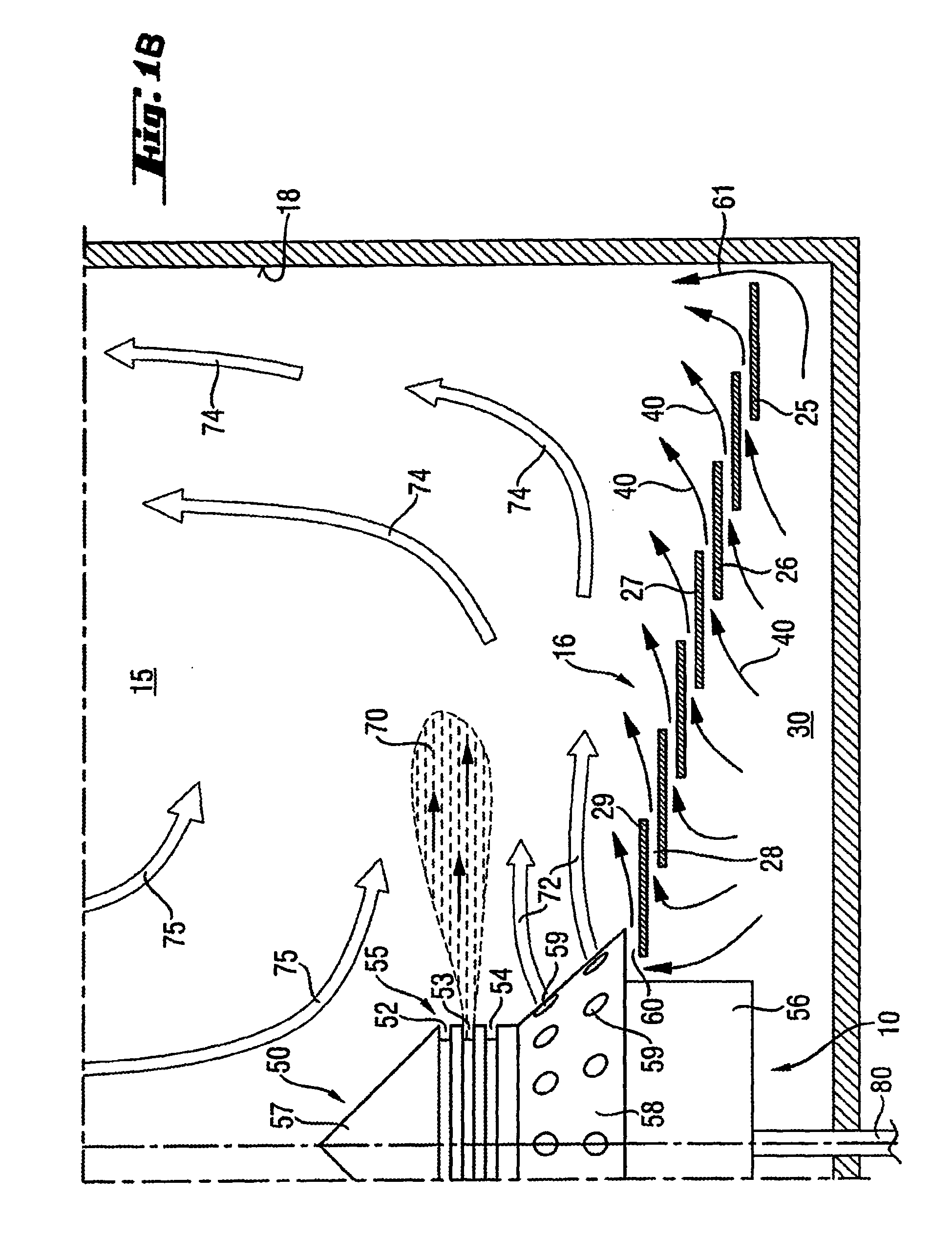
[0191]The bottom 16 is composed of a total of seven annular ring plates as guide plates, laid one on top of another. The seven ring plates are placed one on top of another such that an outermost ring plate 25 forms a lowermost ring plate, on which the further six inner ring plates are then placed, each of which lying below and some of which overlapping.

[0192]For the sake of clarity, only some of the total of seven ring plates are provided with reference numerals, for example the two ring plates 26 and 27 lying one on top of the other. By virtue of this superposition and spacing, a annular slot 28 is formed in each case between two ring plates, through which pro...


PUM

PropertyMeasurementUnit
temperatureaaaaaaaaaa
thicknessaaaaaaaaaa
temperatureaaaaaaaaaa

Abstract

The present invention relates to a method for producing a shell catalyst which comprises a porous shaped catalyst support body with an outer shell in which at least one catalytically active species is present. In order to provide a shell catalyst production method by means of which shell catalysts can be produced, said shell catalysts having, over a comparatively large region of their shell thickness, a substantially uniform concentration of catalytically active species and having a substantially uniform shell thickness, what is proposed is a method using an device which is designed to generate, by means of a process gas, a fluid bed of shaped catalyst support bodies in which the shaped catalyst support bodies circulate elliptically or toroidally, preferably toroidally, comprising the steps of charging the device with shaped catalyst support bodies and generating a shaped catalyst support body fluid bed by means of a process gas, the shaped catalyst support bodies circulating elliptically or toroidally in the fluid bed, preferably toroidally; impregnating an outer shell of the shaped catalyst support body with a catalytically active species or precursor thereof by spraying the shaped catalyst support bodies circulating elliptically or toroidally in the fluid bed with a solution comprising a catalytically active species or a precursor thereof; drying the shaped catalyst support bodies sprayed with the solution.

Description

CROSS REFERENCE TO RELATED APPLICATIONS[0001]This application is a U.S. National Phase Application of PCT International Application PCT / 2008 / 004328, filed May 30, 2008, which claims priority to German Application DE 102007025442.5, filed May 31, 2007, the contents of both applications being incorporated by reference herein for all purposes.FIELD OF THE INVENTION[0002]The present invention relates to a method for producing a shell catalyst which comprises a porous catalyst support shaped body with an outer shell in which at least one catalytically active species is present.DESCRIPTION OF RELATED ART[0003]Shell catalysts and processes for the preparation thereof are known in the prior art. In shell catalysts, the catalytically active species—and frequently also the promoters—are present only in a more or less broad outer region (shell) of a shaped catalyst support body, i.e. they do not completely penetrate the shaped catalyst support body (cf., for example, EP 565 952 A1, EP 634 214 ...

Claims


Application Information

Patent Timeline
Patent Type & Authority Patents(United States)
IPC IPC(8): B01J21/00B01J23/72B01J23/70H01M4/88B01J29/00B01J25/00B01J23/00B05D7/00B01J2/16B01J23/66B01J35/00B01J37/02C07C67/055
CPCB01J35/008C07C67/055B01J37/0221B01J2/16C07C69/15C07C69/01B01J23/66B01J23/38B01J23/70B01J37/02B01J35/02
Inventor HAGEMEYER, ALFREDMESTL, GERHARDSCHECK, PETERUNGAR, SYBILLE
Owner CLARIANT INT LTD
Why Eureka
Try Eureka