
Method of forming an audio processing system and structure therefor

Active Publication Date: 2015-01-06
SEMICON COMPONENTS IND LLC
View PDF10 Cites 6 Cited by
  • Summary
  • Abstract
  • Description
  • Claims
  • Application Information

AI Technical Summary

Problems solved by technology

Dynamically changing the clock speed, or clock throttling, often resulted in inconsistencies in the period of some or all of the signals derived from the clock.
These inconsisten

Method used


Image

  • Method of forming an audio processing system and structure therefor
  • Method of forming an audio processing system and structure therefor
  • Method of forming an audio processing system and structure therefor

Examples


Example

[0020]For simplicity and clarity of the illustration(s), elements in the figures are not necessarily to scale, and the same reference numbers in different figures denote the same elements, unless stated otherwise. Additionally, descriptions and details of well-known steps and elements are omitted for simplicity of the description. As used herein current carrying electrode means an element of a device that carries current through the device such as a source or a drain of an MOS transistor or an emitter or a collector of a bipolar transistor or a cathode or anode of a diode, and a control electrode means an element of the device that controls current through the device such as a gate of an MOS transistor or a base of a bipolar transistor. Although the devices are explained herein as certain N-channel or P-Channel devices, or certain N-type or P-type doped regions, a person of ordinary skill in the art will appreciate that complementary devices are also possible in accordance with the ...


PUM


Abstract

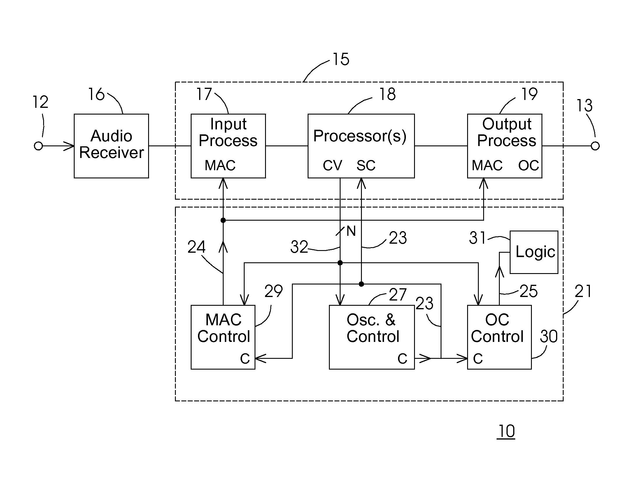
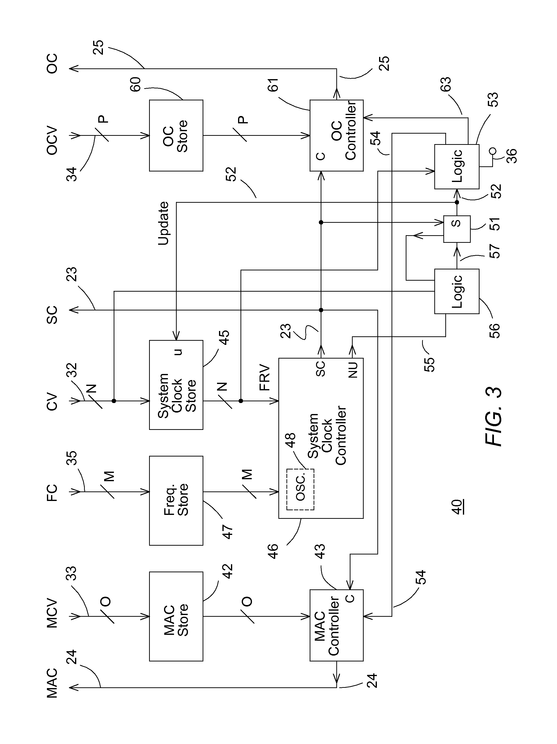
In one embodiment, an audio processing system includes a frequency control block that forms a system clock and a master audio clock. The frequency control block is configured to change a frequency of the system clock and change a relationship between the system clock and the master audio clock so that the frequency of the master audio clock remains substantially constant.

Description

[0001]The present application claims priority to U.S. provisional patent application No. 61 / 777,982 filed on Mar. 12, 2013 entitled METHOD OF FORMING AN AUDIO PROCESSING SYSTEM AND STRUCTURE THEREFOR and having common inventors and which is hereby incorporated herein by reference.[0002]The present application is related to U.S. patent application Ser. No. 13 / 451,267 entitled Method and System For Improving Quality Of Audio Sound, having Dustin Griesdorf as an inventor, and a common assignee, and which is hereby incorporated herein by reference.BACKGROUND OF THE INVENTION[0003]The present invention relates, in general, to electronics, and more particularly, to semiconductors, structures thereof, and methods of forming semiconductor devices.[0004]In the past, the electronics industry utilized various methods and structures to produce audio processing systems for many various types of applications. In some applications, such as portable systems, it was important to conserve power to pr...

Claims


Application Information

Patent Timeline
IPC IPC(8): H03M1/00G06F1/08G06F3/16H03M1/12
CPCH03M1/124G06F1/08H03M1/001G06F3/16G06F1/324G06F1/12Y02D10/00
Inventor COENEN, IVO LEONARDUSDUARTE DE JESUS, PAULO JORGE
Owner SEMICON COMPONENTS IND LLC
Learn More