Polar receiver architecture and signal processing methods

a receiver and signal processing technology, applied in the direction of digital transmission, simultaneous amplitude and angle demodulation, pulse technique, etc., can solve the problems of poor performance and high bit error rate (ber)

Active Publication Date: 2015-01-06
INNOPHASE
View PDF8 Cites 10 Cited by
  • Summary
  • Abstract
  • Description
  • Claims
  • Application Information

AI Technical Summary

Benefits of technology

The patent text describes an improved polar receiver signal processing apparatus and methods. The technical effects of the patent include improved performance and reduced bit error rates of polar receivers by addressing deficiencies in previous proposals. The proposed apparatus and methods include a harmonic ILO and a fundamental ILO, as well as a mixer for combining signals from both ILOs. The use of these components and signal processing techniques can lead to better performance and reliability of polar receivers.

Problems solved by technology

However, the proposed polar receiver architectures and associated signal processing have deficiencies that result in poor performance and high bit error rates (BER).

Method used


Image

  • Polar receiver architecture and signal processing methods
  • Polar receiver architecture and signal processing methods
  • Polar receiver architecture and signal processing methods

Examples


Embodiment Construction

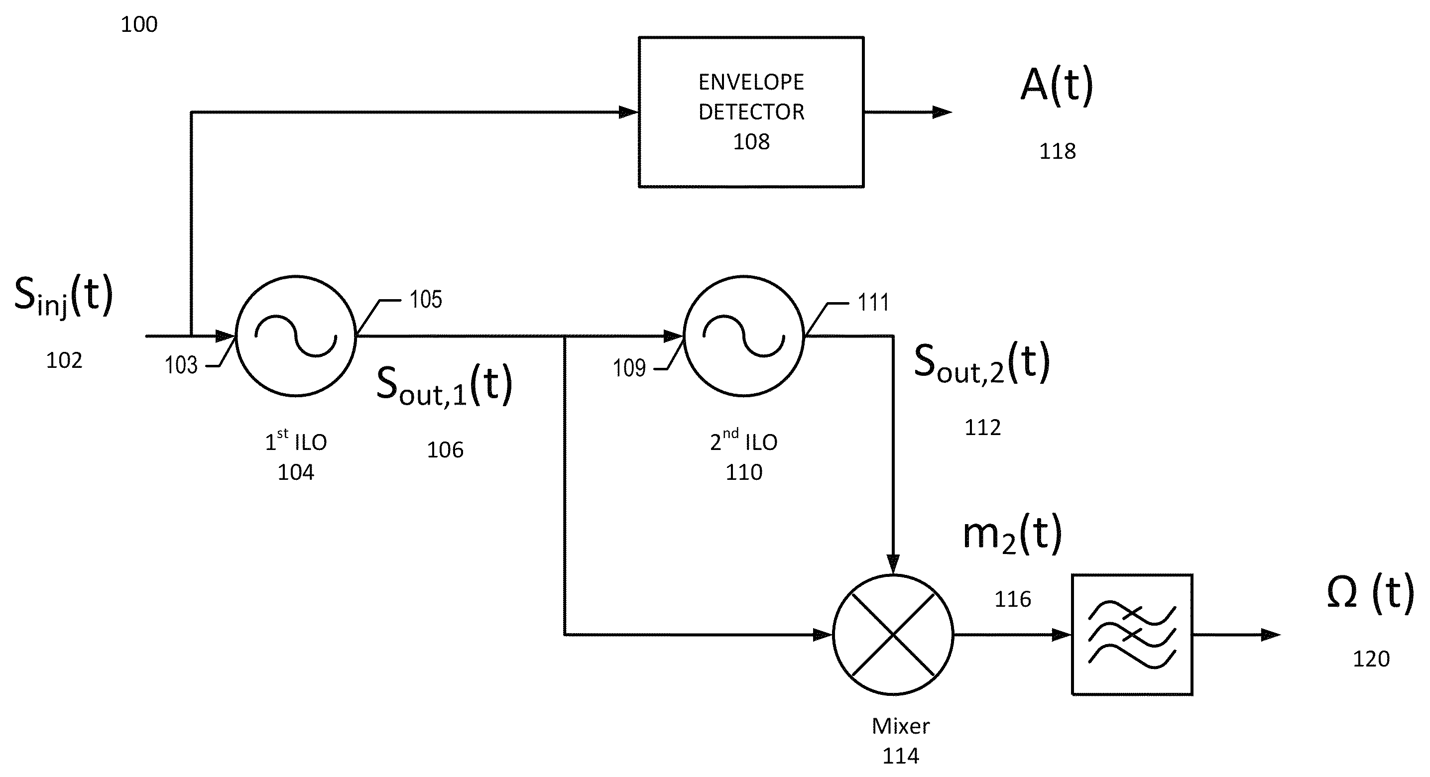
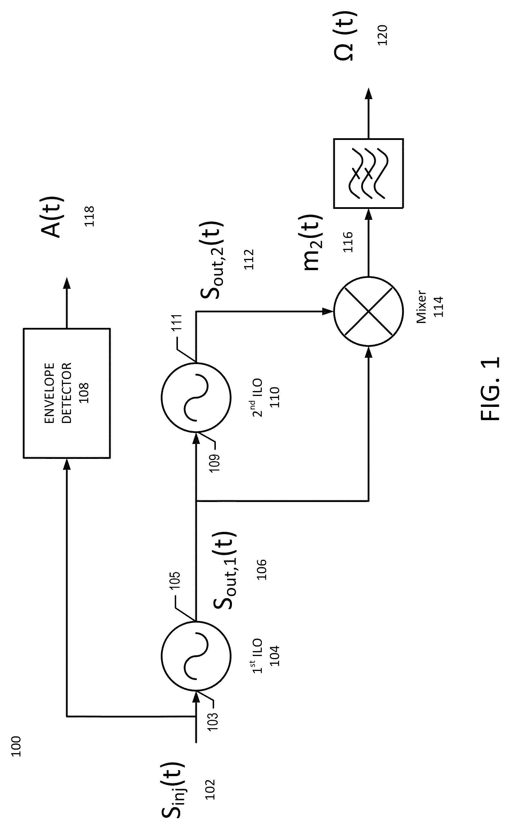
[0015]With reference to FIG. 1, a block diagram of a polar receiver 100 will be described in accordance with some embodiments. The injection signal Sinj(t) 102, which is a received modulated signal having a variable phase component, is applied to an input node 103 of the second harmonic injection locked oscillator (ILO) 104 (also referred to herein as a harmonic ILO). The output signal of the harmonic ILO Sout,1(t) 106 at node 105 has a compressed variable phase component, as will be described below. The compressed variable phase signal 106 is applied to input node 109 of the fundamental injection locked oscillator ILO 110 (also referred to herein as a fundamental ILO), and undergoes a delay to generate the output signal Sout,2(t) 112 at output node 111. That is, Sout,1(t) 106 and Sout,2(t) 112 are related by a time delay imposed by fundamental ILO 110. Sout,1(t) 106, which is the phase compressed signal, and Sout,2(t) which is the delayed phase compressed signal, are applied to mix...


PUM


Abstract

Compressing a variable phase component of a received modulated signal with a second harmonic injection locking oscillator, and generating a delayed phase-compressed signal with a fundamental injection locking oscillator, and combining the phase-compressed signal and the delayed phase-compressed signal to obtain an estimated derivative of the variable phase component, and further processing the estimated derivative to recover data contained within the received modulated signal.

Description

CROSS REFERENCE TO RELATED APPLICATIONS[0001]This application is related to the following co-pending applications, filed on even date herewith, all of which are incorporated herein by reference in their entirety: Ser. No. 13 / 839,557, filed Mar. 15, 2013, entitled POLAR RECEIVER SIGNAL PROCESSING APPARATUS AND METHODS; Ser. No. 13 / 839,462 filed Mar. 15, 2013, entitled LNA WITH LINEARIZED GAIN OVER EXTENDED DYNAMIC RANGE; Ser. No. 13 / 840,379 filed Mar. 15, 2013, entitled DIGITALLY CONTROLLED INJECTION LOCKED OSCILLATOR; and, Ser. No. 13 / 842,470, filed Mar. 15, 2013, entitled SINGLE-BIT DIRECT MODULATION TRANSMITTER.BACKGROUND OF THE INVENTION[0002]Communications transceivers may utilize numerous architectures to recover data from a modulated carrier signal. These architectures include coherent demodulation, using either intermediate frequency conversion or direct-conversion receivers. Such receivers typically recover or regenerate the communications carrier signal using a phase-locked...

Claims


Application Information

Patent Timeline
Patent Type & Authority Patents(United States)
IPC IPC(8): H03D3/18H03D3/00H04L27/227
CPCH03D3/007H04L27/227H04L27/389H03B5/1228H03B5/1215H03B5/1243H03D1/22H03D5/00H03B2200/007H03B2200/0074H04L27/2272
Inventor XU, YANGMUNOZ HERMOSO, SARA
Owner INNOPHASE
Why Eureka
Try Eureka