Bulldozer

a bulldozer and rear mounting technology, which is applied in the direction of electric propulsion mounting, mechanical machines/dredgers, and jet propulsion mounting, etc., can solve the problems of increasing the vibration transmission to the duct from the engine, shortening the life of the parts around these connecting parts, and shortening the vertical distance between the duct and the rear mounting part. , the effect of reducing the vibration load

Active Publication Date: 2015-01-13
KOMATSU LTD
View PDF46 Cites 7 Cited by
  • Summary
  • Abstract
  • Description
  • Claims
  • Application Information

AI Technical Summary

Benefits of technology

[0006]For stable support of an air cleaner, it is preferred that the air cleaner be mounted on the engine cover. However, in this case, depending on the difference between the vibration transmitted to the duct from the engine and the vibration transmitted to the duct from the air cleaner, there is a load on the duct. In particular, since the engine is supported with a mounting part, the amount of vibration transmitted to the duct from the engine increases as the distance between the mounting part and the duct increases. As a result, as the load increases on the connecting part between the engine and the duct or the connecting part between the air cleaner and the duct, the life of the parts around these connecting parts may be shortened.
[0007]An object of the present invention is to provide a bulldozer capable of reducing the load from vibration to the duct connected to the air cleaner.
[0009]In the embodiment of the present invention, the rear mounting part is situated higher than the front mounting part. Thus, compared to a case that the rear mounting part is situated at the same height as the front mounting part, the vertical distance between the duct and the rear mounting part is short. Therefore, the load on the duct from vibration can be reduced.

Problems solved by technology

However, in this case, depending on the difference between the vibration transmitted to the duct from the engine and the vibration transmitted to the duct from the air cleaner, there is a load on the duct.
In particular, since the engine is supported with a mounting part, the amount of vibration transmitted to the duct from the engine increases as the distance between the mounting part and the duct increases.
As a result, as the load increases on the connecting part between the engine and the duct or the connecting part between the air cleaner and the duct, the life of the parts around these connecting parts may be shortened.

Method used


Image

  • Bulldozer
  • Bulldozer
  • Bulldozer

Examples


Embodiment Construction

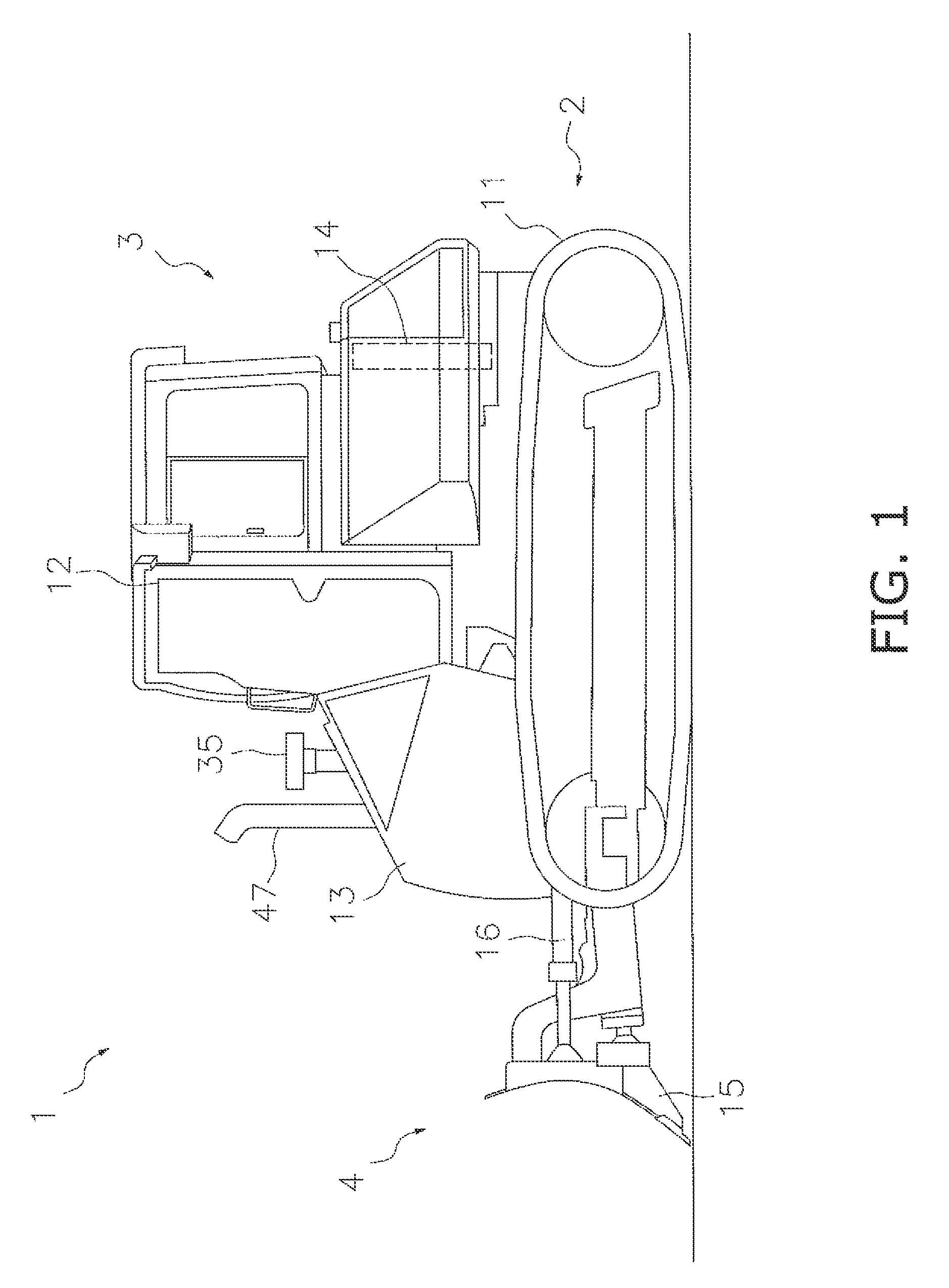
[0019]The side view of bulldozer 1 relating to the embodiment of the present invention is shown in FIG. 1. This bulldozer 1 is equipped with a traveling device 2, a vehicle body 3 and a work implement 4. The traveling device 2 is a device that runs the bulldozer and has crawler belts 11. The bulldozer 1 runs when the crawler belts 11 are driven.

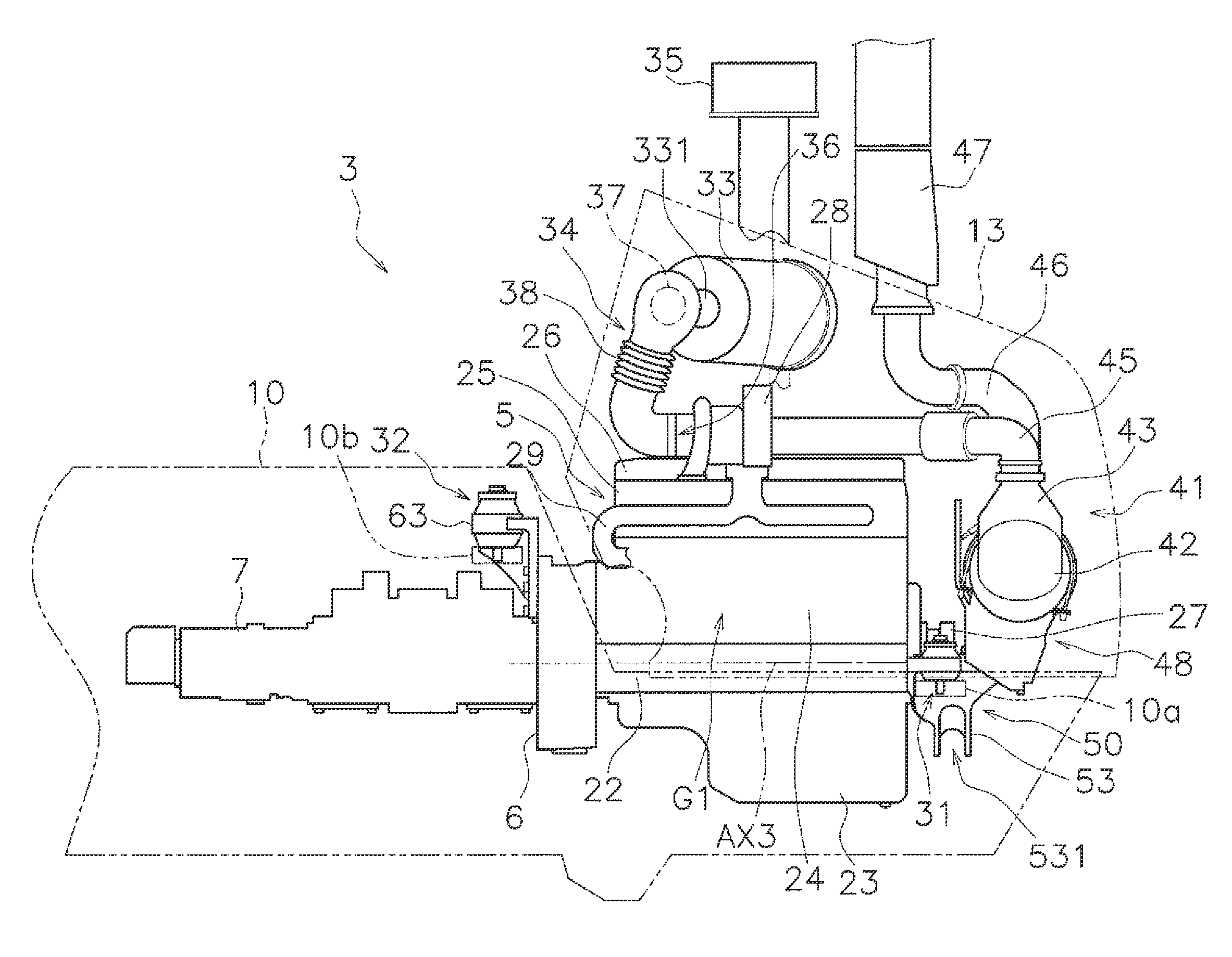
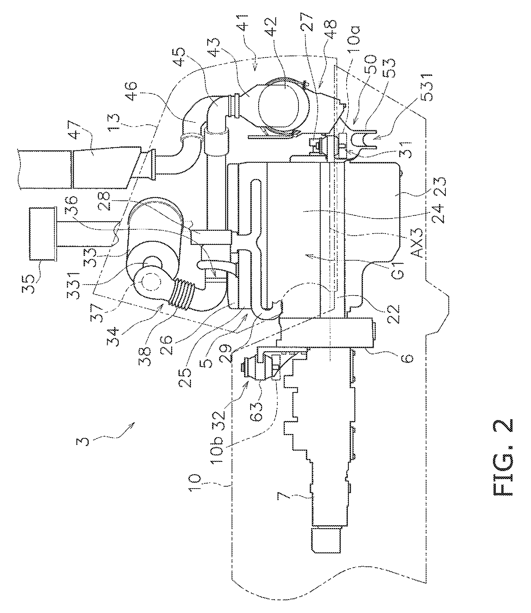
[0020]The vehicle body 3 includes a body frame 10 (refer to FIG. 2 and FIG. 5), a cab 12, an engine cover 13 and a cooling device 14. The engine cover 13 is situated in front of the cab 12. An engine 5 described later is in the engine cover 13. The top surface of the engine cover 13 is inclined towards the front and downward. The cooling device 14 is situated behind the cab 12. In general, cooling devices are situated in front of the engine inside the engine cover in front of cabs in bulldozers. The cooling device 14 includes, for example, a radiator to cool a cooling fluid of the engine 5 and an oil cooler to cool an operating fluid.

[0021]Th...


PUM


Abstract

The cab is situated on the body frame. The engine cover is situated in front of the cab. The engine includes the crankshaft extending in the longitudinal direction of the bulldozer. The air cleaner is situated above the engine. The air cleaner is secured to the engine cover. The duct connects the air cleaner and the engine. The duct includes the first connector and the second connector. The first connector is connected to the engine. The second connector is connected to the air cleaner. The front mounting part supports the engine on the body frame. The rear mounting part supports the engine on the body frame. The rear mounting part is situated behind and above the front mounting part.

Description

CROSS-REFERENCE TO RELATED APPLICATIONS[0001]This application claims priority under 35 U.S.C. §119 to Japanese Patent Application No. 2012-098568, filed on Apr. 24, 2012. The entire disclosure of Japanese Patent Application No. 2012-098568 is hereby incorporated herein by reference.BACKGROUND[0002]1. Field of the Invention[0003]The present invention relates to a bulldozer.[0004]2. Background Information[0005]Bulldozers are equipped with a cab, engine cover and engine. The engine cover is situated in front of the cab. The engine is situated inside the engine cover. Additionally, an air cleaner is connected to the engine by a duct. For example, a bulldozer with an air cleaner situated above the engine is disclosed in Japan Laid-open Patent Application Publication No. JP-A-2002-21565.SUMMARY[0006]For stable support of an air cleaner, it is preferred that the air cleaner be mounted on the engine cover. However, in this case, depending on the difference between the vibration transmitted ...

Claims


Application Information

Patent Timeline
Patent Type & Authority Patents(United States)
IPC IPC(8): B60K5/00B62D25/08E02F3/76E02F9/08
CPCE02F9/0866E02F3/7609E02F9/0891B62D21/11B62D55/06B62D25/082
Inventor SAKAI, KIYOTAKAMIZUNO, TAISUKEASAKA, HIROKAZU
Owner KOMATSU LTD
Why Eureka
Try Eureka