Method of mineral fuel beneficiation with subsequent delivery to the consumer by pipeline transportation

a technology of mineral fuel and pipeline transportation, which is applied in the direction of transportation and packaging, dismantling machines, lighting and heating equipment, etc., can solve the problems of fundamental decline of adverse environmental impact and the total power consumed by mining facilities, and achieve the effects of reducing power intensity, increasing productivity, and simplifying operation

Inactive Publication Date: 2015-01-13
ENKHBOLD CHULUUN
View PDF5 Cites 1 Cited by
  • Summary
  • Abstract
  • Description
  • Claims
  • Application Information

AI Technical Summary

Benefits of technology

[0029]The present invention is aimed at the decrease of the power intensity and increase of productivity, simplification of functioning and improvement of reliability of the entire mining and power generating system, avoiding solid fuel losses throughout the whole technological line and elimination of some intermediate elements of this line, improvement of consumer properties of fossil coal delivered to the destination point, increase of coal use completeness, providing the transportation channel uninterruptible operation in winter, as well as reducing the unfavorable impact of entire mining and power generating system on the environment.
[0032]Mainly due to performing the beneficiation process in the immediate vicinity of the mining face, the beneficiation of fossil fuel, in particular, coal, with subsequent delivery to the consumer using the above-described method results in drastic reduction of total power consumed by this mining facility and fundamental decline of its adverse environmental impact due to the elimination of displacement (especially along the vertical) of huge waste rock volumes by large distances, to say nothing of clearing the territory around the mine from waste rock piles. Placing the tails of this underground beneficiation process in the waste space not only prevents falling of the earth surface and associated irreparable damage of all objects located within the zone of underground mining works, but delivers cost-free filling mass for these mining works as well, thus allowing to control geomechanical processes of overlying rock motion.
[0033]Mining mass grinding in liquid medium having a density intermediate between those of coal and waste rock, with the separation of coal and waste rock in this medium followed by deep beneficiation of fossil fuel in the same heavy fuel allows to prevent further destruction of coal lumps requiring no further size reduction. This sparing mode of grinding not only contributes to energy consumption reduction, but substantially increases the yield of most valuable coal grades free from coal fines as well, thus improving the quality of product. Combined with the utilization of a part of coal-contained methane, non-freezable carrier medium, a drastic decrease of pipeline transport power consumption and maximum possible preservation of initial size of material delivered by pipeline, the process suggested allows to reduce the cost of solid fuel supplied to various consumers, and simultaneously to improve the main consumer properties of coal.

Problems solved by technology

Mainly due to performing the beneficiation process in the immediate vicinity of the mining face, the beneficiation of fossil fuel, in particular, coal, with subsequent delivery to the consumer using the above-described method results in drastic reduction of total power consumed by this mining facility and fundamental decline of its adverse environmental impact due to the elimination of displacement (especially along the vertical) of huge waste rock volumes by large distances, to say nothing of clearing the territory around the mine from waste rock piles.

Method used


Image

  • Method of mineral fuel beneficiation with subsequent delivery to the consumer by pipeline transportation
  • Method of mineral fuel beneficiation with subsequent delivery to the consumer by pipeline transportation
  • Method of mineral fuel beneficiation with subsequent delivery to the consumer by pipeline transportation

Examples


example 1

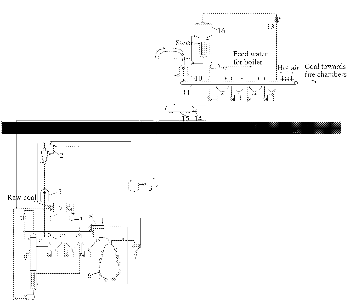
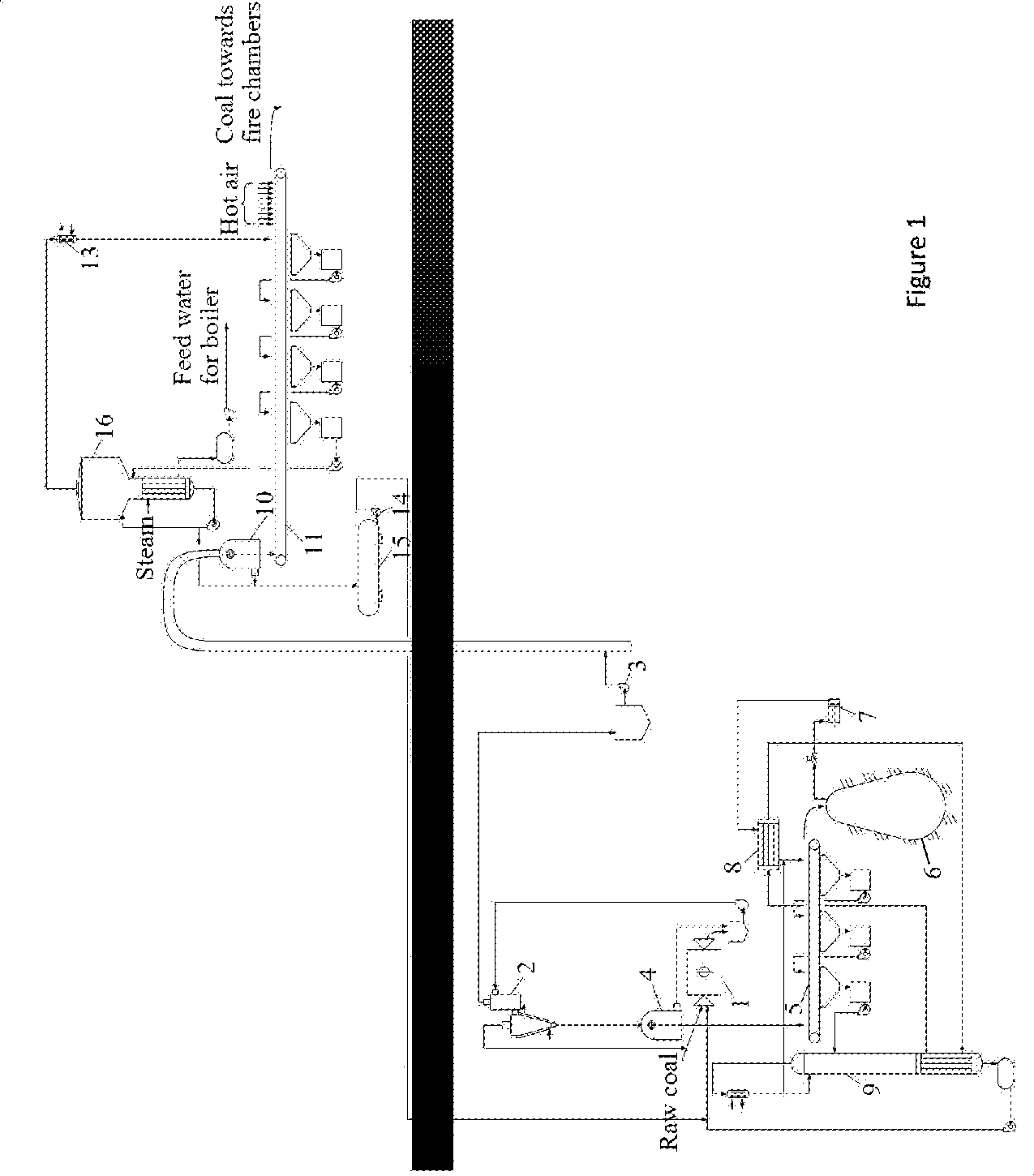
[0060]FIG. 1 shows the flow diagram of underground treatment process of the initial rock portion that requires additional size reduction under deep mining conditions, where the rock remains sufficiently heated by heat of interior the whole year round, irrespective of meteorological conditions, and when the coal produced is intended for a power plant.

[0061]This portion of initial rock separated by screening and requiring additional size reduction to improve waste rock separation is ground in rattler 1 flooded with liquid whose density is intermediate between those of fossil fuel and rock refuse. The rattler operates in closed cycle with three-product heavy-media hydrocyclone 2.

[0062]Liquid represents an aqueous solution of calcium nitrate / zinc chloride mixture having a density of 1.48 g / cm3.

[0063]The beneficiated product, leaving hydrocyclone 2 remains suspended in heavy aqueous medium, which first brings the product to a pitbottom, and then by pump 3 and ground pumping stations (not...

example 2

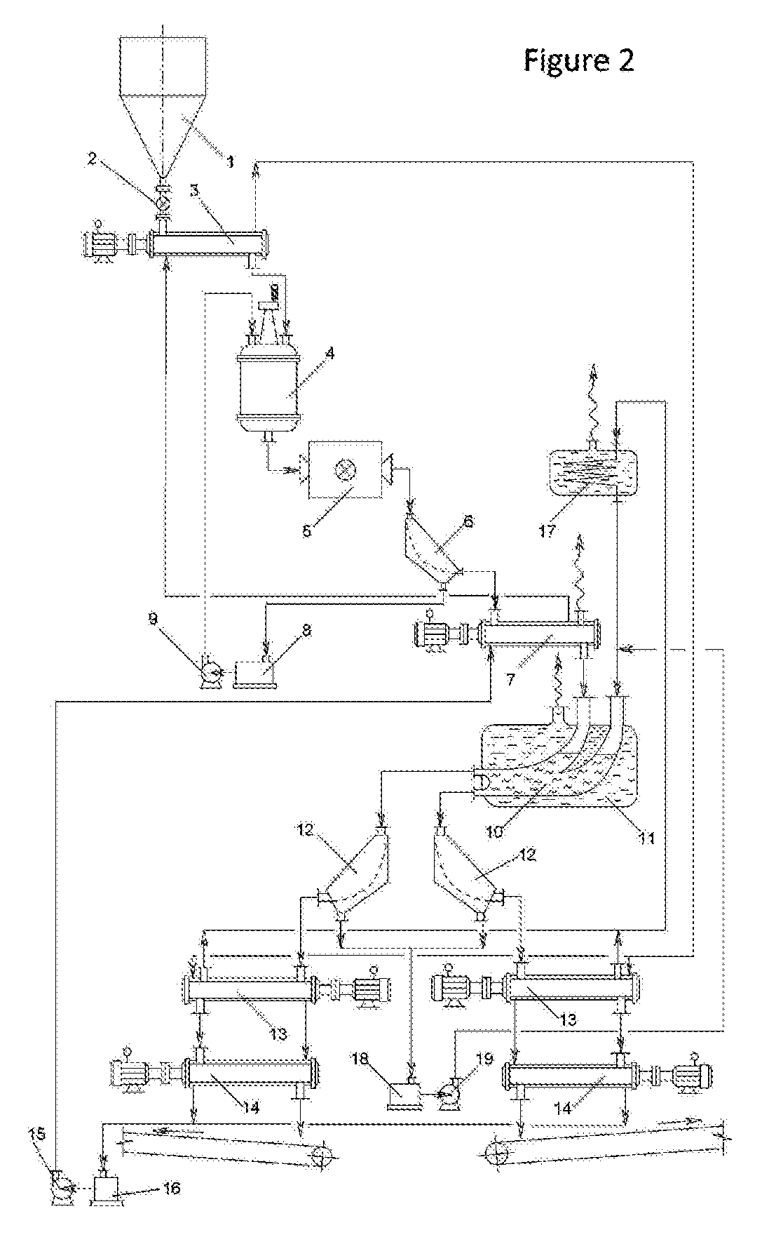
[0075]FIG. 2 shows the flow diagram of underground beneficiation of powder-like mass resisting highly selective dry separation. Treating this part of raw material in aqueous solutions of mineral salts results in the reduction of separation efficiency due to increased effect of water-salt medium rheological characteristics on highly dispersed material, while, a high humidity of paste-like beneficiation products leads to the increase of power consumption associated with the discharge of dry coal and dry final tails.

[0076]In this case, liquid argon, non-aqueous cryogenic liquid with a density intermediate between those of fossil fuel and rock refuse, is used as a separating medium. The boiling point of this liquid is so low that the discharge of dry beneficiation products takes place automatically due to irreversible boiling-up of liquid phase residues due to contact with the environment.

[0077]To this end, initial powder-like run-of-mine coal is fed from bin 1 through gate 2 to recuper...

example 3

[0088]On FIG. 3 is represented the basic technological scheme of joint delivery lumpy and powdery coal from mine on surface in case the consumer of such firm fuel is the thermal power station.

[0089]Coal delivered in main stream from mining faces to the shaft bottom is classified on separator 1 into lumpy material and fines comprising both fine pieces of coal and all its dusty fractions.

[0090]Coal fines separated from lumps and large pieces are fed by screw feeder 2 equipped with a heat-exchange jacket to press mold 3 for pressing. A moderate amount of pitch is introduced into screw feeder 2 as a binding additive, which strengthens monolithic blocks made from coal fines in the form of cylindrical bodies resembling pistons of hydraulic facilities by their shape. Steam for heating coal mixture with pitch before pressing is fed into its heat-exchange jacket.

[0091]Batches of lumpy coal and coal blocks apiece are alternately arranged in loading chamber 4 of the loading system of transport...


PUM

PropertyMeasurementUnit
water freezing temperatureaaaaaaaaaa
densityaaaaaaaaaa
densityaaaaaaaaaa

Abstract

A method of mineral fuel beneficiation with subsequent delivery to the consumer by pipeline transportation relates fuel and energy complex and can find application in coal and slate energetics. Invention main objective is security of solid fuel delivery from mine (or an open cut coal mine) in already enriched form, with its subsequent through delivery to the consumer by pipeline on any distances in stream mode, without any intermediate transshipment operations. For this purpose use liquid with set complex physical, sanitary-and-hygienic and ecological properties, simultaneously, in 4 qualities: As environment for grinding material that needed further reduction of size; As separation environment for the subsequent, after reduction of size, deep underground gravitational enrichment of combustible mineral, As motionless filler of the vertical pipeline, for buoyancy in it ready product from mine on terrestrial surface: As carrying medium for final drift of end-product to the consumer by main pipeline. Depending on consumer type of solid fuel, a time of year, and weather conditions in which such, non-polluting, mining-energetic complex functions, there are used various technological approaches as to the general principles of construction of such, non-polluting, beneficiating transport technological process as well as within the limits of separate links of such technological chain, various methods of the regeneration, used many functional liquids which are in the closed contour of circulation between producer of solid fuel and its consumer.

Description

BACKGROUND OF THE INVENTION[0001]1. Field of the Invention[0002]The present invention relates to mining of different kinds of power generating fossils and can be used in coal, shale mining, and other branches of mining industry connected to solid fuel consumers via transportation infrastructure facilities.[0003]2. Description of Related Art[0004]The traditional method of providing various consumers with coal or another solid mineral fuel is well known. To this end, the run-of-mine coal is delivered to the earth surface storage by skip hoists and concentrated at a coal-concentrating plant. Then, thus produced high-quality solid fuel is shipped from the finished product storage to the consumer via railway transport.[0005]Cleaned coal arrived to the destination point is discharged from cars, piled up at open areas, and then delivered for its direct application (see, e.g., Golitsyn M. V., M. B Golitsyn A. M. Everything About Coal. Moscow, Nauka Publishers, 1989.-192 pp.)[0006]The above ...

Claims


Application Information

Patent Timeline
Patent Type & Authority Patents(United States)
IPC IPC(8): E21C41/18B03B9/00C10L1/32C10L9/00C22B1/00E21C41/16E21F13/00F23K1/02F23K3/02
CPCB03B9/005C10L1/326C10L9/00C22B1/00F23K1/02F23K3/02B03B9/00E21C41/16E21F13/002
Inventor ENKHBOLD, CHULUUNALEXANDER, BRODT
Owner ENKHBOLD CHULUUN
Why Eureka
Try Eureka