ESD protection device

a protection device and shielding technology, applied in the direction of overvoltage protection resistors, emergency protective arrangements for limiting excess voltage/current, spark gap details, etc., can solve the problems of electronic components being protected, overvoltage typified, electronic apparatus becoming an important technical problem, etc., to achieve excellent discharge properties, small electrostatic capacitance, and high durability

Inactive Publication Date: 2015-01-13
TDK CORPARATION
View PDF9 Cites 4 Cited by
  • Summary
  • Abstract
  • Description
  • Claims
  • Application Information

AI Technical Summary

Benefits of technology

[0028]According to the present invention, it is possible to provide an ESD protection device that not only has small electrostatic capacitance and an excellent discharge property but also has high durability against repeated use with the occurrence of short-circuiting between electrodes after discharge inhibited. In addition, according to the present invention, the heat resistance and the weatherability can also be enhanced, and furthermore, a thinner devise can be achieved compared with conventional ones, and the productivity and the economy can also be enhanced.

Problems solved by technology

Therefore, the protection of electronic components from overvoltage typified by electrostatic pulses generated when a human body comes into contact with a terminal of an electronic apparatus has become an important technical problem.
However, the varistor generally has large electrostatic capacitance, and therefore, when it is used in a high-speed transmission system, it becomes a factor in degrading signal quality.
On the other hand, a problem of the ESD protection device is that breakage (melting, deformation, and the like) occurs easily in the electrodes and their periphery (hereinafter simply referred to as the “electrode periphery”) due to heat and stress generated by discharge.

Method used


Image

  • ESD protection device
  • ESD protection device
  • ESD protection device

Examples


first embodiment

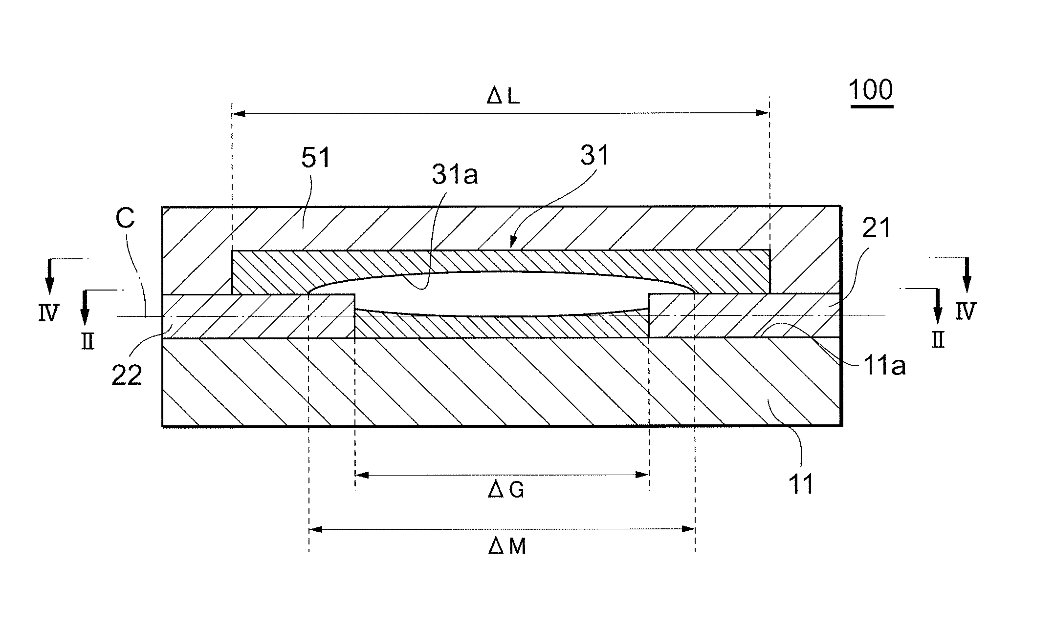
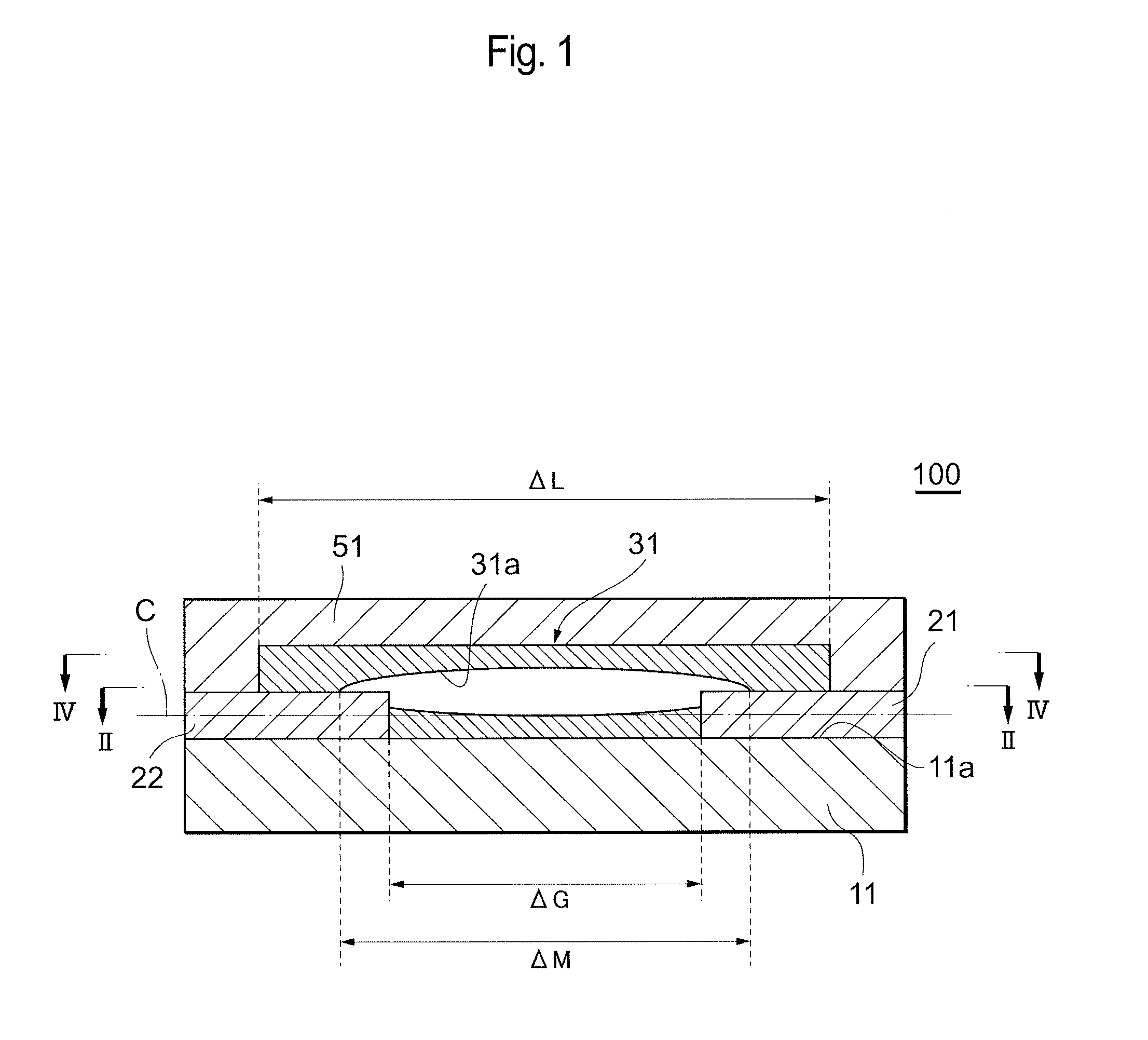
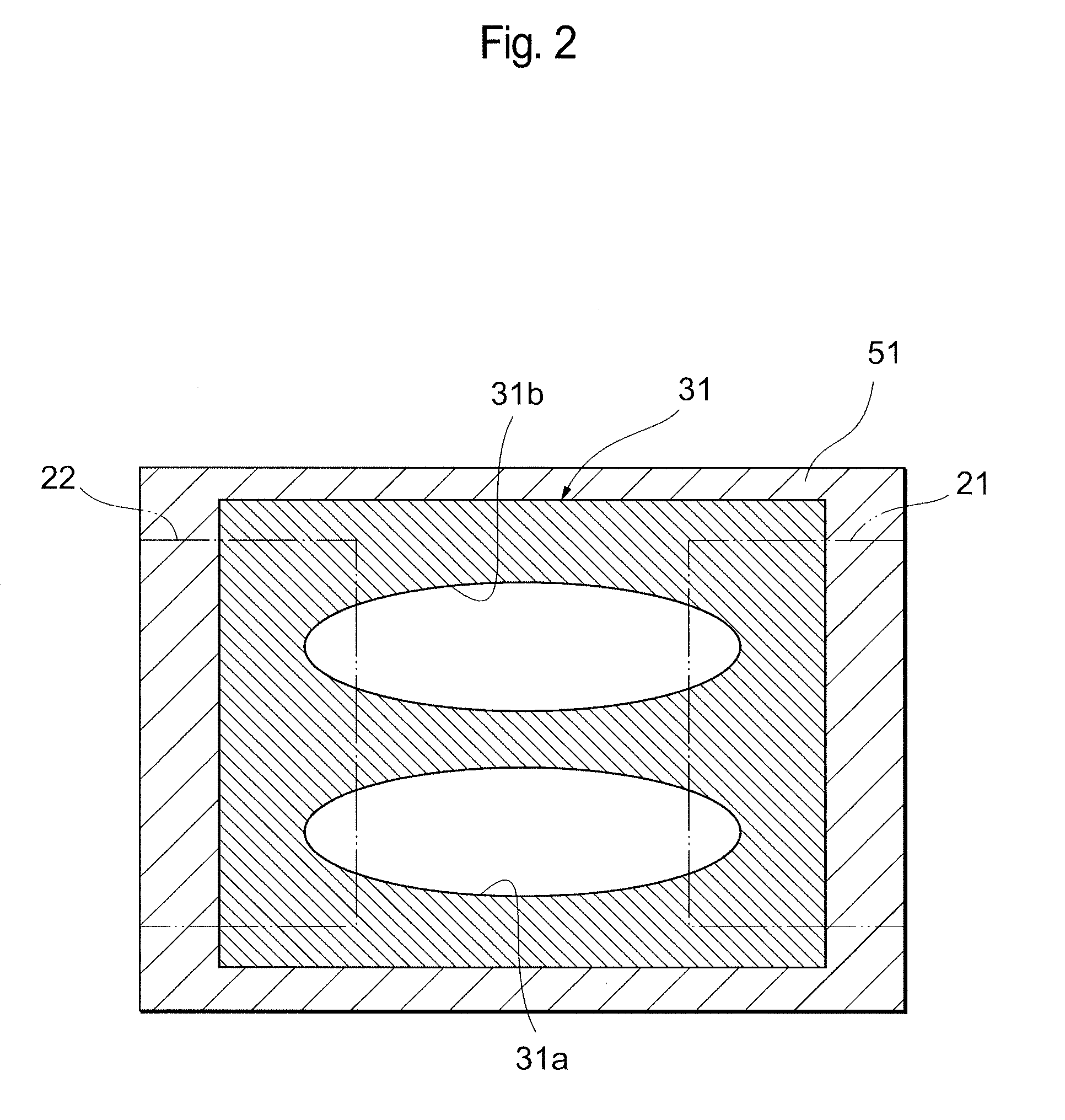
[0042]FIG. 1 is a schematic sectional view schematically showing an ESD protection device in the present embodiment, and FIG. 2 is a sectional view taken along the line II-II in FIG. 1.

[0043]An ESD protection device 100 includes an insulating substrate 11, paired electrodes 21 and 22 disposed on this insulating substrate 11, a discharge induction section 31 disposed between these electrodes 21 and 22, terminal electrodes 41 (see FIG. 7) electrically connected to the electrodes 21 and 22, and an insulating protection layer 51 formed so as to cover the discharge induction section 31. The discharge induction section 31 is composed of a porous body, in which micropores are discontinuously scattered, and has a hollow structure having at least one or more hollow sections 31a and 31b. Here, the paired electrodes 21 and 22 are located so that their tip portions are exposed in these hollow sections 31a and 31b. In this ESD protection device 100, the discharge induction section 31 functions a...

example 1

[0067]First, as shown in FIG. 5, a green sheet (manufactured by TDK Corporation) obtained by sheeting a material composed mainly of Al2O3 and a glass component was prepared as an insulating substrate 11, and an Ag paste was printed with about a thickness of 20 μm on one insulating surface 11a of the insulating substrate 11 by screen printing to pattern-form paired band-like electrodes 21 and 22 arranged opposite each other. For the paired electrodes after the printing, the length and width of the electrodes 21 and 22 were 0.5 mm and 0.4 mm respectively, and the gap distance ΔG between the electrodes 21 and 22 was 30 μm.

[0068]Next, as shown in FIG. 6, a discharge induction section 31 was formed on the above insulating substrate 11 and on the above electrodes 21 and 22 by the following procedure.

[0069]First, 10 vol % of glass particles composed mainly of SiO2 (manufactured by Nihon Yamamura Glass Co., Ltd., product number: ME13) as an insulating inorganic material 32, 30 vol % of Al2O...

example 2

[0073]A discharge induction section 31 that was composed of a porous body, in which micropores 34 were discontinuously scattered, and had a hollow structure having one hollow section 31a was fabricated, and an ESD protection device 100 in Example 2 was obtained, by performing operations similar to those in Example 1 except that the resin paste was screen-printed in an oval spherical shape at only one place during the screen printing of the resin paste.


PUM


Abstract

The present invention provides an ESD protection device that not only has small electrostatic capacitance and an excellent discharge property but also has high durability against repeated use with the occurrence of short-circuiting between electrodes after discharge inhibited. An ESD protection device including an insulating substrate, electrodes arranged on this insulating substrate away from and opposite each other, and a discharge induction section located between these electrodes, wherein the discharge induction section is composed of a porous body, in which micropores are discontinuously scattered, and has a hollow structure having at least one or more hollow sections.

Description

CROSS-REFERENCES TO RELATED APPLICATIONS[0001]This application relates to and claims priority from Japanese Patent Application No. 2010-221411, filed on Sep. 30, 2010, the entire disclosure of which is incorporated herein by reference.TECHNICAL FIELD[0002]The present invention relates to an ESD protection device and particularly to an ESD protection device that is useful for use in a high-speed transmission system and combination with a common mode filter.BACKGROUND ART[0003]In recent years, the size reduction and performance enhancement of electronic apparatuses have been rapidly in progress. In addition, there has been significant progress in increasing transmission speed (an increased frequency exceeding 1 GHz) and reducing driving voltage, as typically seen in high-speed transmission systems, such as USB2.0, S-ATA2, and HDMI. On the other hand, the withstand voltage of electronic components used in electronic apparatuses decreases with the size reduction of electronic apparatuse...

Claims


Application Information

Patent Timeline
Patent Type & Authority Patents(United States)
IPC IPC(8): H02H9/00H01C7/12H01T1/20H01T4/12H02H9/04
CPCH01C7/12H01T1/20H01T4/12H02H9/041H01C7/10H05F3/00
Inventor ASAKURA, KENSAKUSUZUKI, SHINGOHIROBE, YASUHIRO
Owner TDK CORPARATION
Why Eureka
Try Eureka