Alignment detection device

a detection device and alignment technology, applied in the direction of resistor details, transmission monitoring, instruments, etc., can solve the problems of preventing proper communication between the antenna and the antenna signal, obstructing the signal distortion in the antenna signal,

Active Publication Date: 2015-01-13
TOWER
View PDF11 Cites 43 Cited by
  • Summary
  • Abstract
  • Description
  • Claims
  • Application Information

AI Technical Summary

Problems solved by technology

Obstruction of the signal distortion in the antenna signal and prevent proper communication between the antenna and the system in communication with the antenna.

Method used


Image

  • Alignment detection device
  • Alignment detection device
  • Alignment detection device

Examples


Embodiment Construction

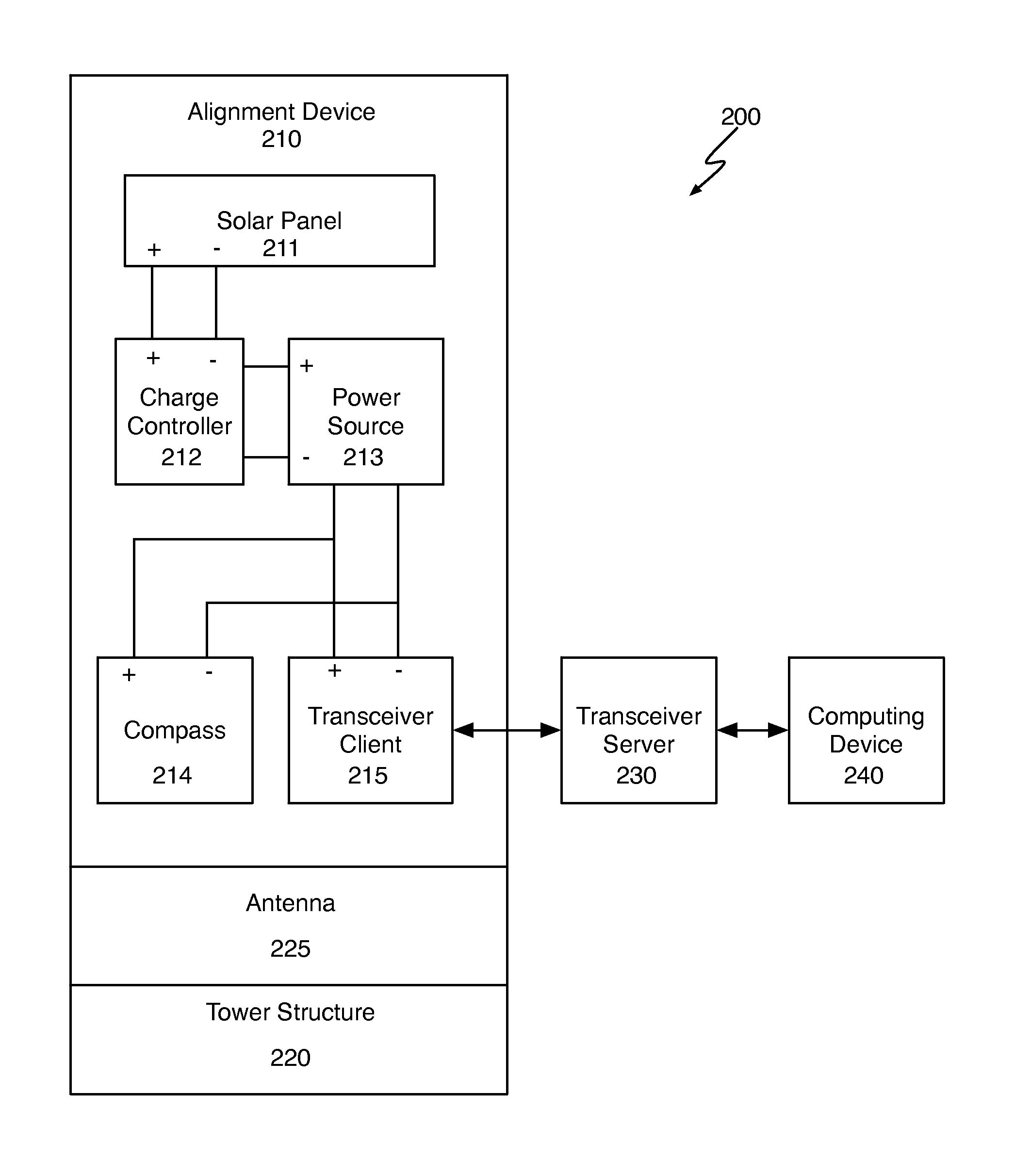
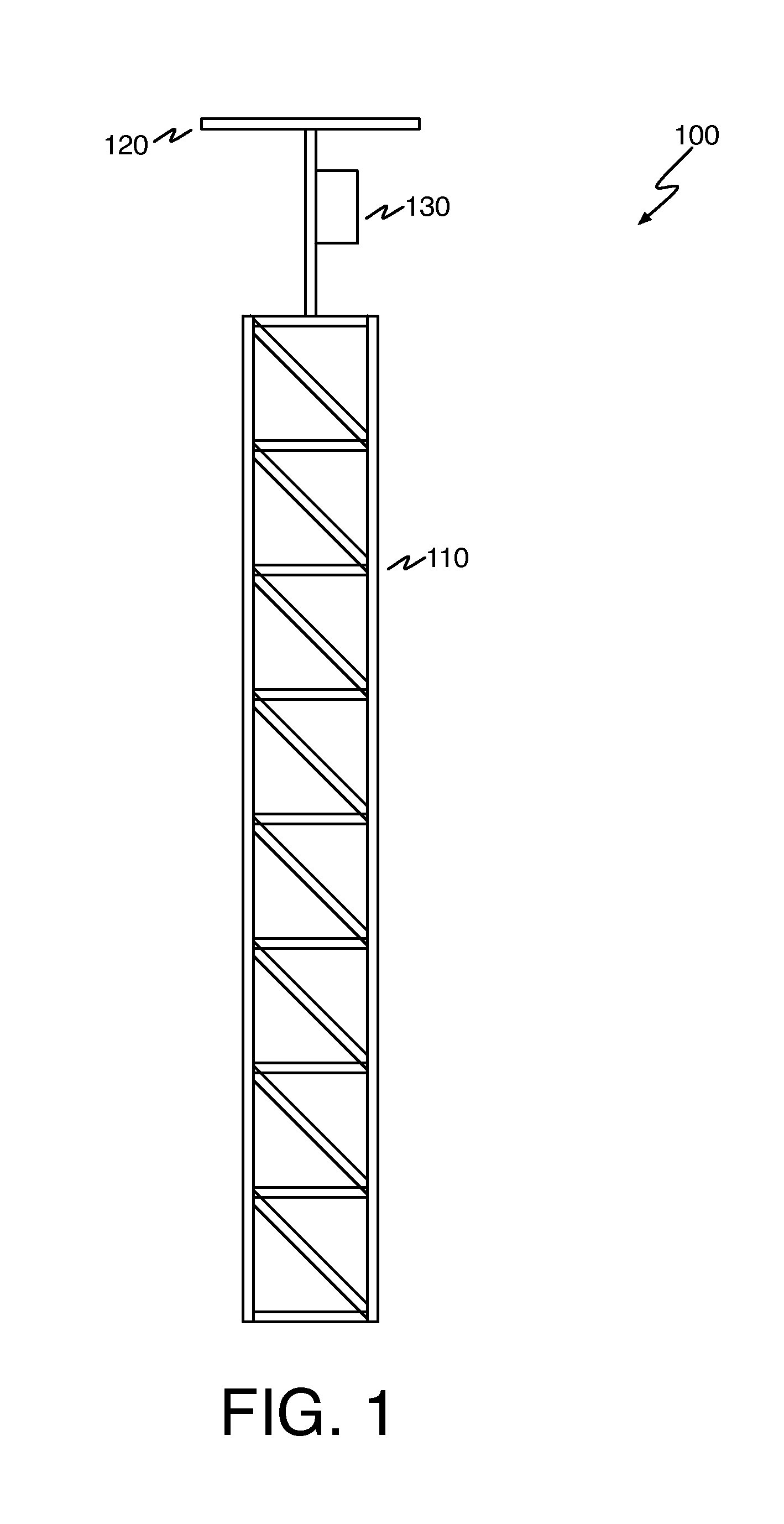
[0015]FIG. 1 illustrates an exemplary extendable structure having an alignment device. The extendable structure 100 of FIG. 1 includes an extendable structure 110, an antenna 120 and an alignment device 130. The extendable structure may be a tower or any other structure that may be extendable. The structure may be extendable by a controller which may be operated by a user, manually by a user, or in some other manner. In some embodiments, the structure 110 may be implemented by an unextendable structure.

[0016]The antenna 120 may be mounted to a portion of the extendable structure, such as an end that is extended vertically away from the ground. When extended, the structure may position the antenna to communicate with a system while avoiding obstructions such as trees and buildings.

[0017]In some embodiments, the device mounted to the structure may be any device (in place of or in addition to antenna device 120) that may be oriented as a result of a bore sight operation. For example, t...


PUM


Abstract

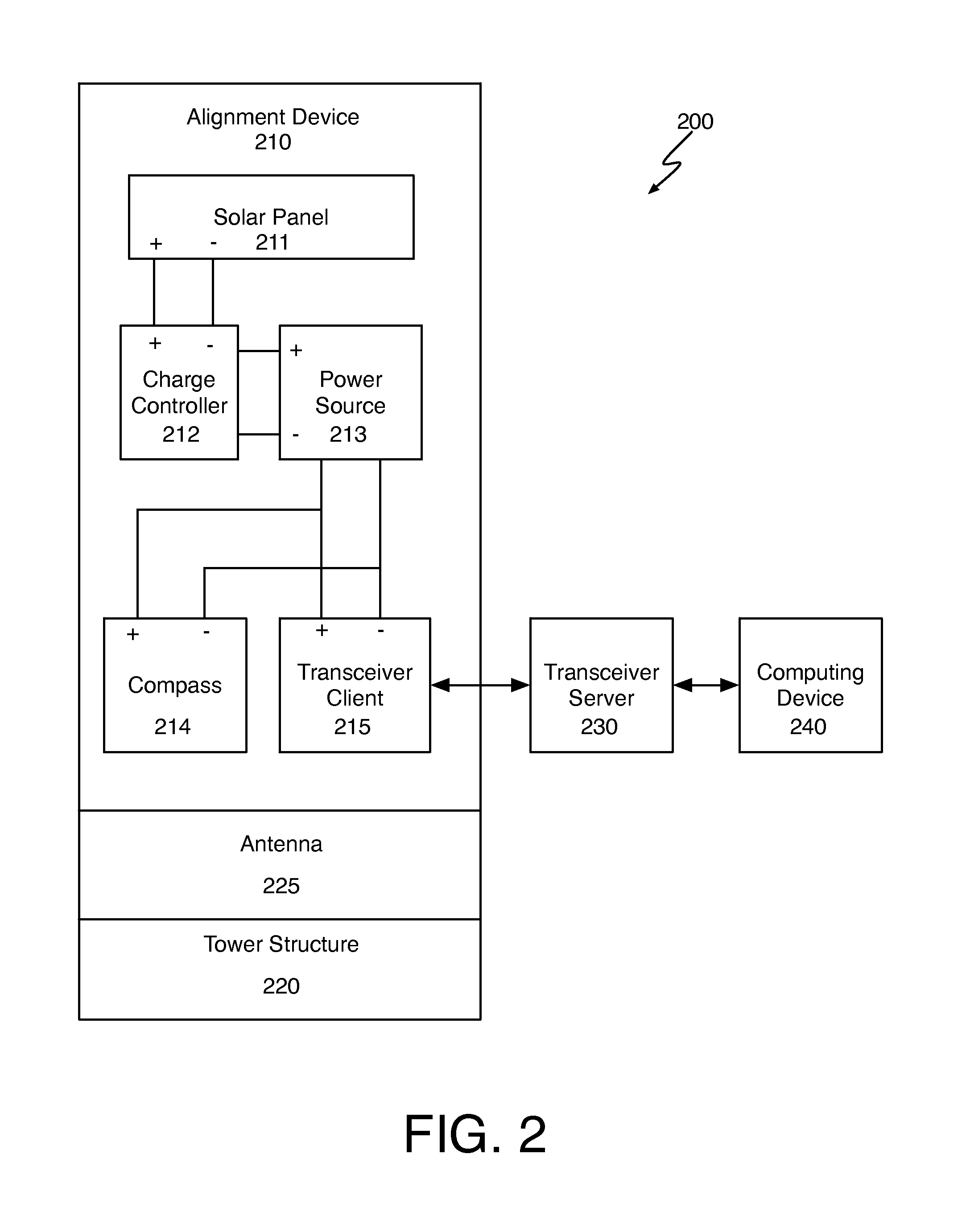
An alignment device provides position information for an antenna coupled to an extendable tower. The alignment device can provide position data including pitch data, roll data, and azimuth data. The position data can be collected at multiple times, and reported to a remote computing device. The position data can be reported as the raw measured data, a delta between two sets of position data, or other data. The alignment device may be solar powered and include a transceiver client for communicating with a remote computing device via a transceiver server.

Description

CROSS REFERENCE TO RELATED APPLICATIONS[0001]The present application is claims the priority benefit of U.S. provisional patent application 61 / 419,513, filed Dec. 3, 2010, and titled “Wireless Solar Compass Antenna Alignment System”, the disclosure of which is incorporated herein by reference.BACKGROUND[0002]Narrow band antennas are used to communicate with a broad array of systems. The communication requires that the narrow band antennas be directed towards the particular system. The direction may be set by performing a bore sight operation on the antenna to direct the antenna communication waves towards the system intended to receive the antenna signal.[0003]Narrow band antennas should be directed towards a system for communication to occur. Therefore, it is important that the line of communication be as free as possible from interference and objects that obstruct the signal. Obstruction of the signal distortion in the antenna signal and prevent proper communication between the ant...

Claims


Application Information

Patent Timeline
Patent Type & Authority Patents(United States)
IPC IPC(8): G06F15/00H01C1/125H01Q1/12H01Q3/00H01Q3/02
CPCH01Q1/125H01Q3/005H01Q3/02H01C1/125
Inventor STISSER, DARYL A.
Owner TOWER
Why Eureka
Try Eureka