Electric motor driven tool for orthopedic impacting

a technology of electric motors and tools, applied in the field of electric motor driven tools for orthopedic impacting, can solve the problems of surgeons suffering from fatigue in this approach, inability to accurately locate and configure the cavity, and clumsy and unpredictable approach, and achieve the effect of enhancing the skill of existing surgeons in guiding instruments and better fitting for prostheses or implants

Active Publication Date: 2015-01-20
MEDICAL ENTERPRISES LTD
View PDF19 Cites 35 Cited by
  • Summary
  • Abstract
  • Description
  • Claims
  • Application Information

AI Technical Summary

Benefits of technology

[0009]In view of the foregoing disadvantages of the prior art, an electric motor-driven orthopedic impacting tool configured to include all the advantages of the prior art and to overcome the drawbacks inherent therein is provided. The tool may be used by orthopedic surgeons for orthopedic impacting in hips, knees, shoulders and the like. The tool is capable of holding a broach, chisel, or other end effector and gently tapping the broach, chisel or other end effector into the cavity with controlled percussive impacts, resulting in a better fit for the prosthesis or the implant. Further, the control afforded by such an electrically manipulated broach, chisel, or other end effector allows adjustment of the impact settings according to a particular bone type or other profile of a patient. The tool additionally enables proper seating or removal of the prosthesis or the implant into or out of an implant cavity and advantageously augments the existing surgeon's skill in guiding the instrument.
[0011]In a further embodiment, the handle may be repositionable or foldable back to the tool to present an inline tool wherein the surgeon pushes or pulls on the tool co-linearly with the direction of the broach. This has the advantage of limiting the amount of torque the surgeon may put on the tool while it is in operation. In a further refinement of the hand grip, there may be an additional hand grip for guiding the surgical instrument and providing increased stability during the impacting operation.
[0012]In a further embodiment, the broach, chisel or other end effector can be rotated to a number of positions while still maintaining axial alignment. This facilitates the use of the broach for various anatomical presentations during surgery.
[0015]In an embodiment, the tool further comprises a control means, which control means includes an energy adjustment element, and which energy adjustment element may control the impact force of the tool and reduce or avoid damage caused by uncontrolled impacts. The energy may be regulated electronically or mechanically. Furthermore, the energy adjustment element may be analog or have fixed settings. This control means allows for the precise control of the broach machining operation.
[0018]In an embodiment the tool may have a lighting element to illuminate a work area and accurately position the broach, chisel, or other end effector on a desired location on the prosthesis or the implant.
[0020]In an embodiment the tool may also include a detent that retains the striker and which may be activated by a mechanical or electrical means such that the energy per impact from the tool to the surgical end effector is increased. In an embodiment, the characteristics of this detent are such that within 30% of striker movement, the retention force exerted by the detent on the striker is reduced by 50%.

Problems solved by technology

Unfortunately, this approach is clumsy and unpredictable as being subject to the skill of the particular physician.
This approach almost will always inevitably result in inaccuracies in the location and configuration of the cavity.
Additionally, the surgeon suffers from fatigue in this approach due to the constant hammering.
Finally, this approach carries with it the risk that the physician will damage bone structure in unintended areas.
This approach is disadvantageous in that it prevents portability of an impacting tool, for instance, because of the presence of a tethering air line, air being exhausted from a tool into the sterile operating field and fatigue of the physician operating the tool.
Further, this approach, as exemplified in U.S. Pat. No. 5,057,112, does not allow for precise control of the impact force or frequency and instead functions very much like a jackhammer when actuated.
Again, this lack of any measure of precise control makes accurate broaching of the cavity more difficult.
While this approach overcomes the fatiguing and accuracy issues, it suffers from having a very high capital cost and additionally removes the tactile feedback that a surgeon can get from a manual approach.
This invention works quite well, but, in the process of testing it, does not allow for a simple method to reverse the broach should it become stuck in the soft tissue.
Further, the pressure of the air results in large forces in the gear train and linear motion converter components, which large forces lead to premature wear on components.

Method used


Image

  • Electric motor driven tool for orthopedic impacting
  • Electric motor driven tool for orthopedic impacting
  • Electric motor driven tool for orthopedic impacting

Examples


Embodiment Construction

[0030]The best mode for carrying out the present disclosure is presented in terms of its preferred embodiments, herein depicted in the accompanying figures. The preferred embodiments described herein detail for illustrative purposes are subject to many variations. It is understood that various omissions and substitutions of equivalents are contemplated as circumstances may suggest or render expedient, but are intended to cover the application or implementation without departing from the spirit or scope of the present disclosure.

[0031]The terms “a” and “an” herein do not denote a limitation of quantity, but rather denote the presence of at least one of the referenced items.

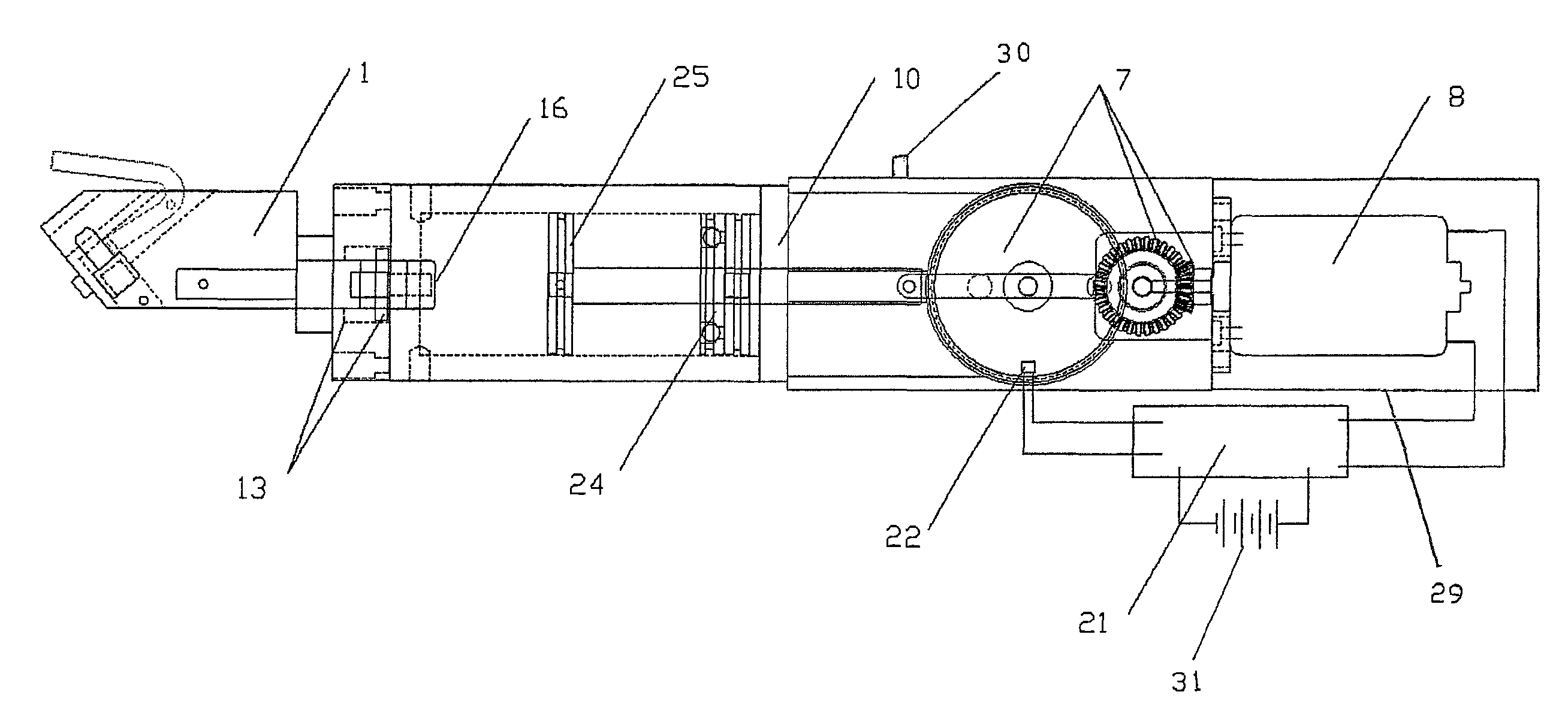
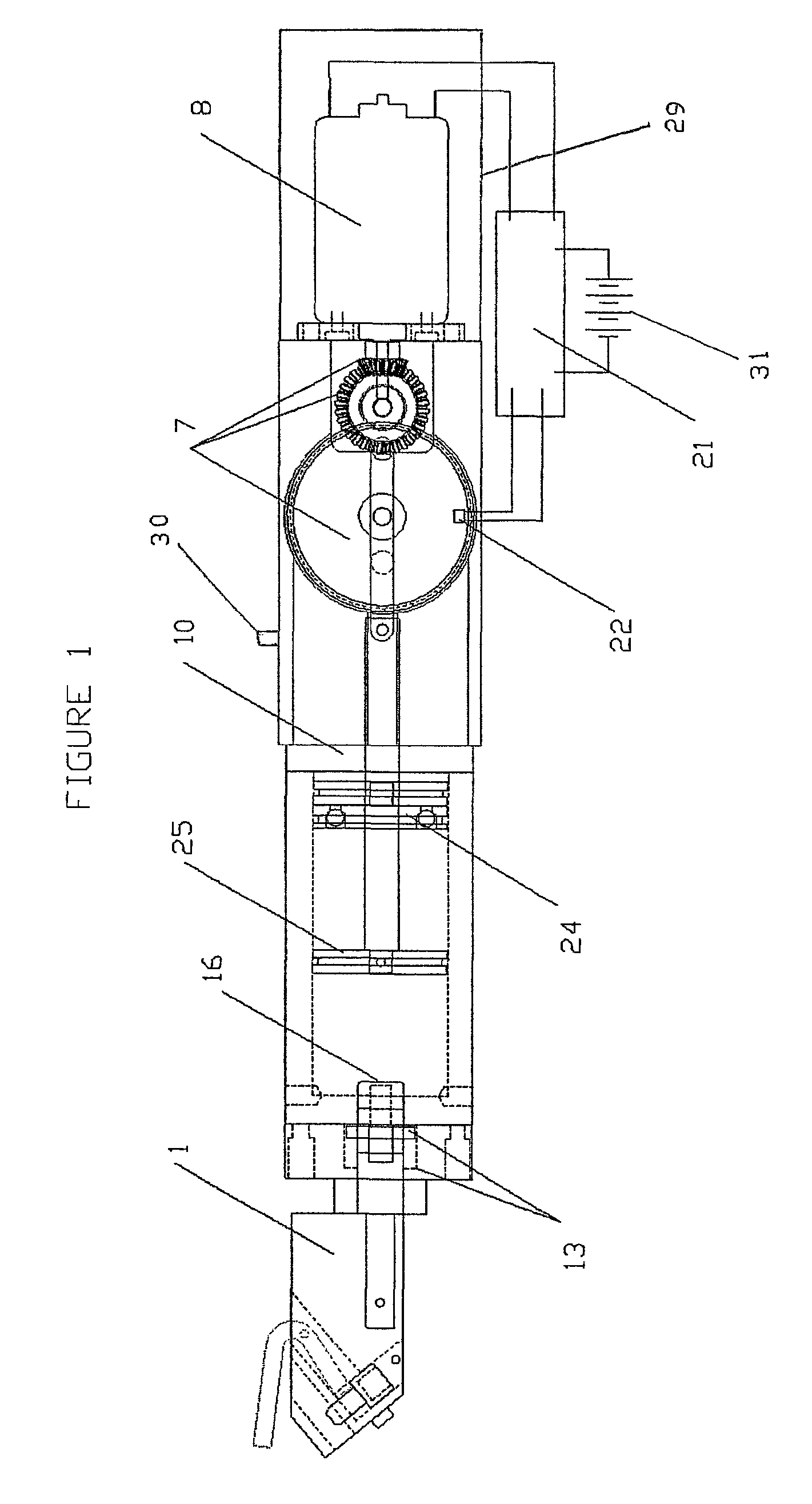
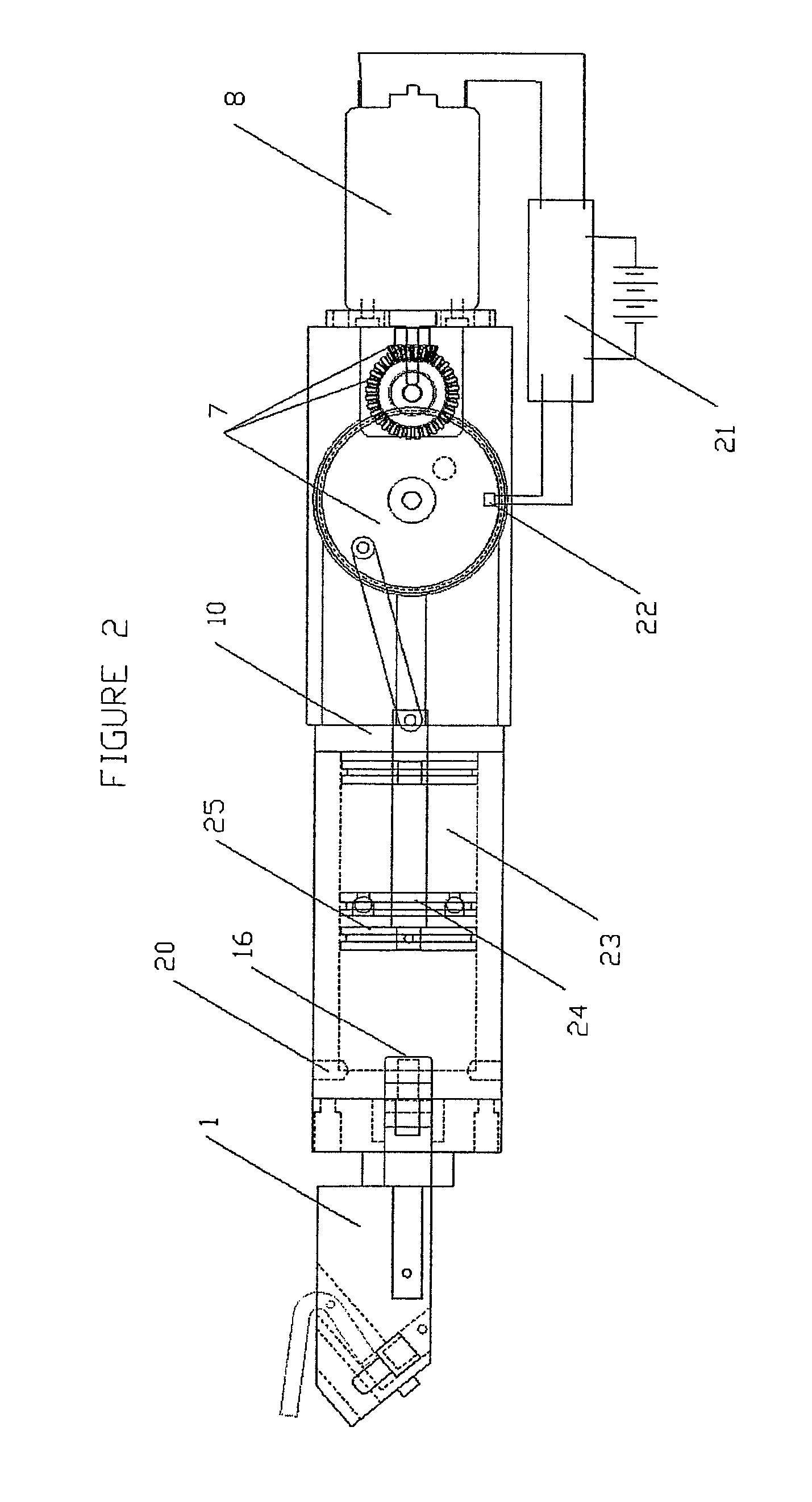
[0032]The present disclosure provides an electric motor-driven orthopedic impacting tool with controlled percussive impacts. The tool includes the capability to perform single and multiple impacts as well as impacting of variable and varying directions, forces and frequencies. In an embodiment the impact force is a...


PUM

PropertyMeasurementUnit
timeaaaaaaaaaa
timeaaaaaaaaaa
forceaaaaaaaaaa

Abstract

An orthopedic impacting tool comprises a motor, an energy storage arrangement, a striker, and an anvil. The motor stores energy in the energy arrangement means and then releases it, causing the striker to apply a controlled force on an adapter to create a precise impact for use in a surgical setting. The tool may further comprise a combination anvil and adapter. The tool further allows forward or backward impacting for expanding the size or volume of the opening or for facilitating removal of a broach, implant, or other surgical implement from the opening. An energy adjustment control of the tool allows a surgeon to increase or decrease the impact energy. A light source and hand grips improve ease of operation of the tool.

Description

CROSS-REFERENCE TO RELATED APPLICATIONS[0001]The present application is a continuation of and claims priority under 35 U.S.C. §120 on the U.S. patent application Ser. No. 14 / 099,467 (now abandoned), filed Dec. 6, 2013, the disclosure of which is incorporated by reference, which '467 application is a divisional application of U.S. patent application Ser. No. 13 / 790,870 (now U.S. Pat. No. 8,602,124), filed on Mar. 8, 2013, the disclosure of which is incorporated by reference, which '870 application was a continuation-in-part of and claimed priority under 35 U.S.C. §120 on U.S. patent application Ser. No. 12 / 980,329 (now U.S. Pat. No. 8,695,726), filed on Dec. 29, 2010, and U.S. patent application Ser. No. 13 / 466,870 (now U.S. Pat. No. 8,393,409), filed on May 8, 2012, the disclosures of which are incorporated by reference.FIELD OF THE DISCLOSURE[0002]The present disclosure relates to electric tools for impacting in orthopedic applications, and, more particularly, to an electric motor ...

Claims


Application Information

Patent Timeline
Patent Type & Authority Patents(United States)
IPC IPC(8): B25D17/00A61B17/16
CPCA61B17/1604A61B2019/521A61B17/1626A61B17/92A61B17/1668A61B17/1628A61B2017/922A61B17/1659A61B2090/309
Inventor PEDICINI, CHRISTOPHER
Owner MEDICAL ENTERPRISES LTD
Why Eureka
Try Eureka