Liquid immersion member, immersion exposure apparatus, liquid recovering method, device fabricating method, program, and storage medium

a technology of immersion exposure and immersion apparatus, which is applied in the direction of microlithography exposure apparatus, printers, instruments, etc., can solve the problems of exposure failure and defective device production, and achieve the effect of preventing defective devices from being produced, forming satisfactorily, and preventing exposure failures from occurring

Active Publication Date: 2015-01-20
NIKON CORP
View PDF32 Cites 1 Cited by
  • Summary
  • Abstract
  • Description
  • Claims
  • Application Information

AI Technical Summary

Benefits of technology

[0007]An object of aspects of the present invention is to provide a liquid immersion member that can satisfactorily form an immersion space. Another object of aspects of the present invention is to provide both an immersion exposure apparatus and a liquid recovering method that can prevent exposure failures from occurring. Yet another object of the present invention is to provide a device fabricating method, a program, and a storage medium that can prevent defective devices from being produced.
[0054]According to the aspects of the present invention, an immersion space can be formed satisfactorily. In addition, according to the aspects of the present invention, it is possible to prevent exposure failures from occurring and thereby to prevent defective devices from being produced.

Problems solved by technology

In the immersion exposure apparatus, exposure failures might occur if, for example, the immersion space cannot be formed in a desired state.
These problems could result in the production of defective devices.

Method used


Image

  • Liquid immersion member, immersion exposure apparatus, liquid recovering method, device fabricating method, program, and storage medium
  • Liquid immersion member, immersion exposure apparatus, liquid recovering method, device fabricating method, program, and storage medium
  • Liquid immersion member, immersion exposure apparatus, liquid recovering method, device fabricating method, program, and storage medium

Examples


Embodiment Construction

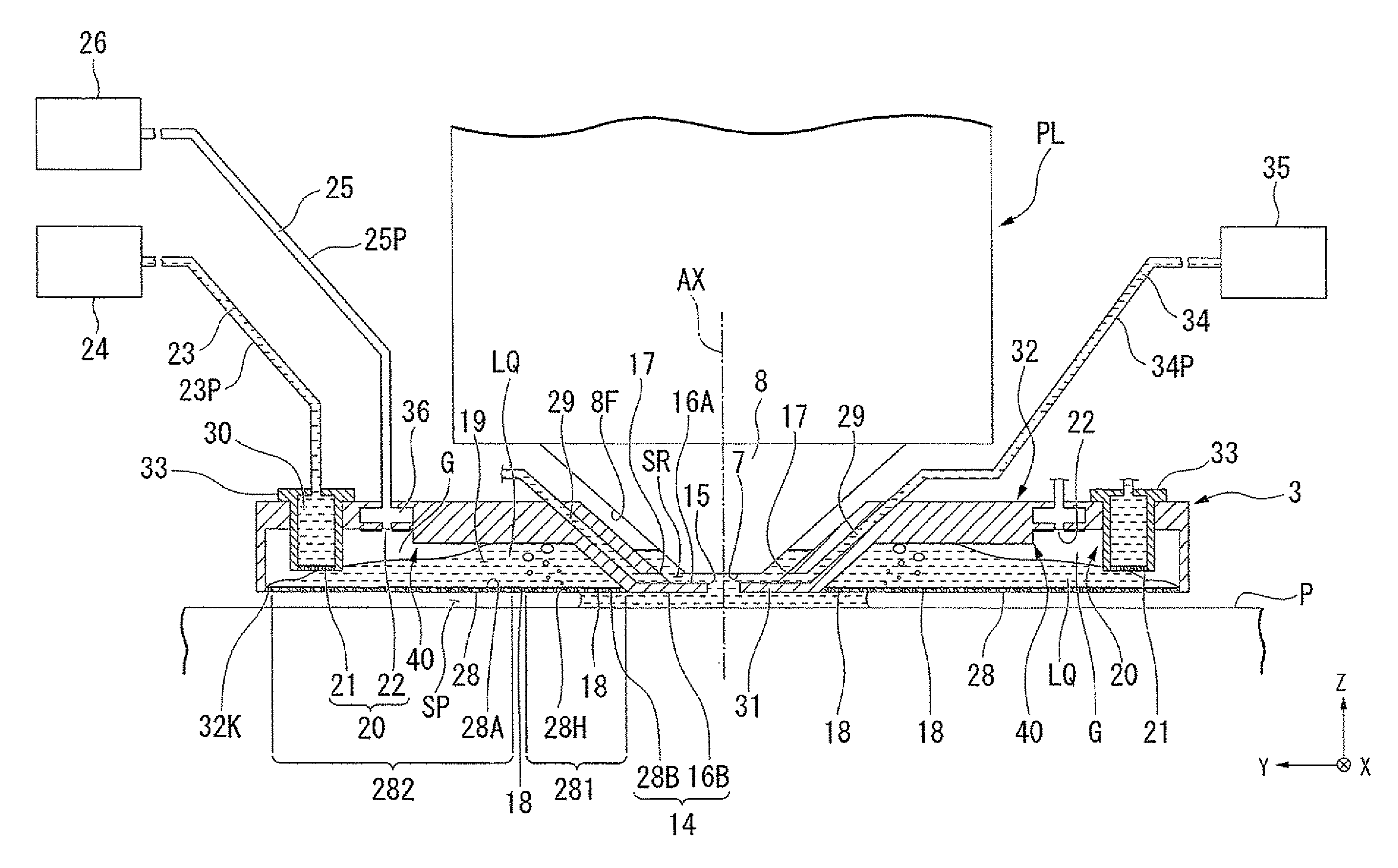
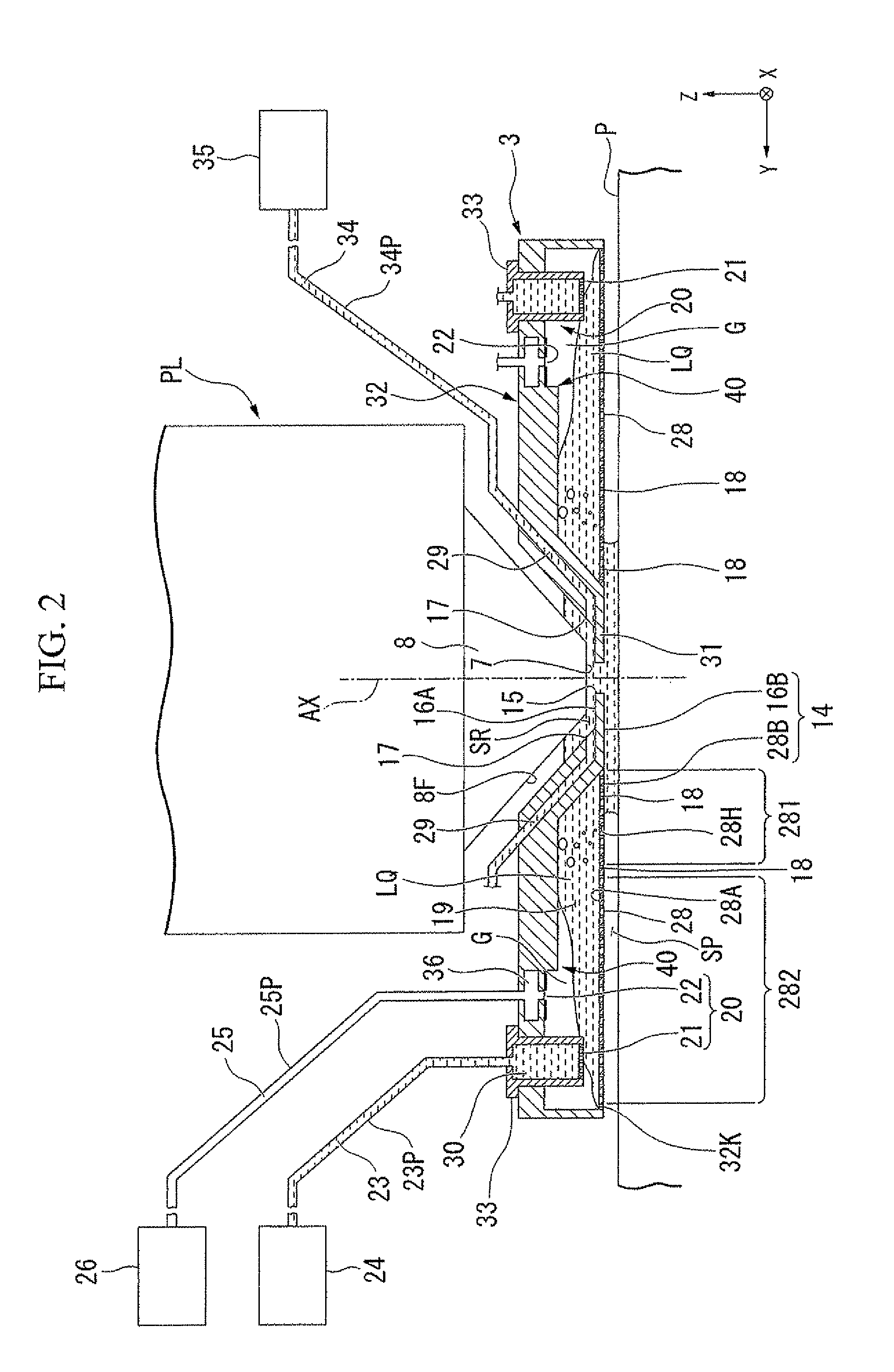
[0109]The embodiments of the present invention will now be explained, referencing the drawings; however, the present invention is not limited thereto. The explanation below defines an XYZ orthogonal coordinate system, and the positional relationships among parts are explained referencing this system. Prescribed directions within the horizontal plane are the X axial directions, directions orthogonal to the X axial directions in the horizontal plane are the Y axial directions, and directions orthogonal to the X axial directions and the Y axial directions (i.e., the vertical directions) are the Z axial directions. In addition, the rotational directions (i.e., the tilting directions) around the X, Y, and Z axes are the θX, θY, and θZ directions, respectively.

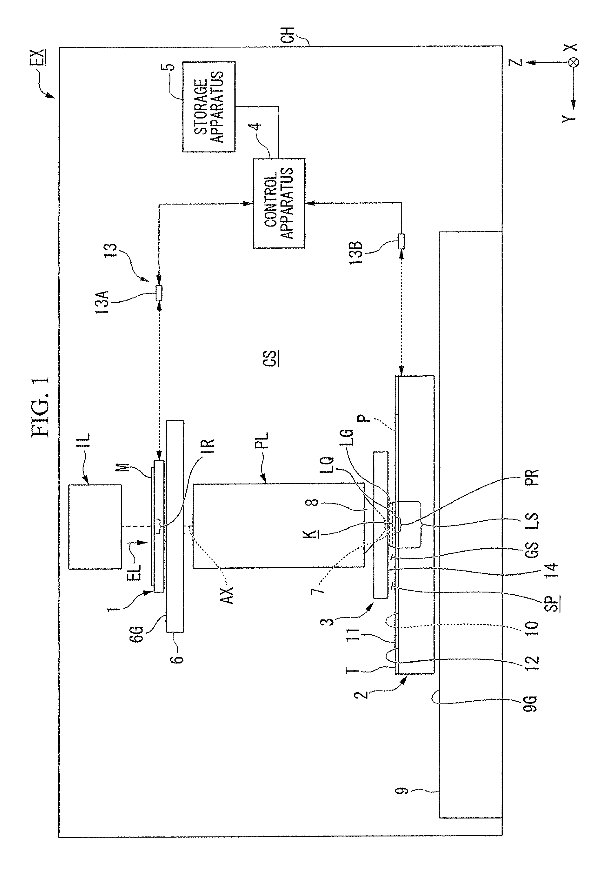
[0110]A first embodiment will now be explained. FIG. 1 is a schematic block diagram that shows one example of an exposure apparatus EX according to a first embodiment. The exposure apparatus EX of the present embodiment is an immers...


PUM

PropertyMeasurementUnit
wavelengthaaaaaaaaaa

Abstract

A liquid immersion member is disposed inside an immersion exposure apparatus and at least partly around an optical member and around an optical path of exposure light that passes through a liquid between the optical member and an object. The liquid immersion member comprises: a first member, which has a first surface, a second surface that faces a direction other than that faced by the first surface, and a plurality of holes that connects the first surface and the second surface, that recovers at least some of the liquid from the space above the object opposing the first surface via the holes; a recovery passageway, wherethrough the liquid recovered via the holes of the first member flows; and a discharge part, which separately discharges a liquid and a gas from the recovery passageway. The first member comprises a first portion and a second portion. The second portion hinders a gas flowing from a space between the object and the first surface into the recovery passageway via the holes more than the first portion does.

Description

CROSS-REFERENCE TO RELATED APPLICATION[0001]This application is a non-provisional application claiming priority to and the benefit of U.S. provisional application No. 61 / 364,136, filed Jul. 14, 2010. The entire contents of which are incorporated herein by reference.BACKGROUND[0002]1. Field of the Invention[0003]The present invention relates to a liquid immersion member, an immersion exposure apparatus, a liquid recovering method, a device fabricating method, a program, and a storage medium.[0004]2. Description of Related Art[0005]As disclosed in, for example, U.S. Patent Application Publication No. 2009 / 0046261, among exposure apparatuses used in photolithography, an immersion exposure apparatus is known that exposes a substrate with exposure light through a liquid in an immersion space.SUMMARY[0006]In the immersion exposure apparatus, exposure failures might occur if, for example, the immersion space cannot be formed in a desired state. These problems could result in the production...

Claims


Application Information

Patent Timeline
Patent Type & Authority Patents(United States)
IPC IPC(8): G03F7/20G03B27/52
CPCG03F7/70341G03F7/709
Inventor SATO, SHINJI
Owner NIKON CORP
Why Eureka
Try Eureka