Supercharge Your Innovation With Domain-Expert AI Agents!

Pressure sensor device having bump chip carrier (BCC)

a pressure sensor and chip carrier technology, applied in the direction of fluid pressure measurement, acceleration measurement using interia forces, instruments, etc., can solve the problems of high cost and reliability issues of existing pressure sensor packaging techniques

Active Publication Date: 2015-01-27
NXP USA INC
View PDF17 Cites 3 Cited by
  • Summary
  • Abstract
  • Description
  • Claims
  • Application Information

AI Technical Summary

Benefits of technology

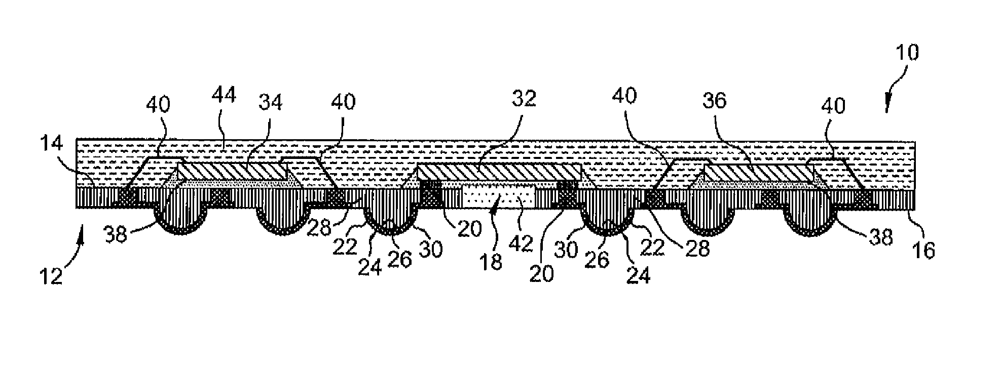
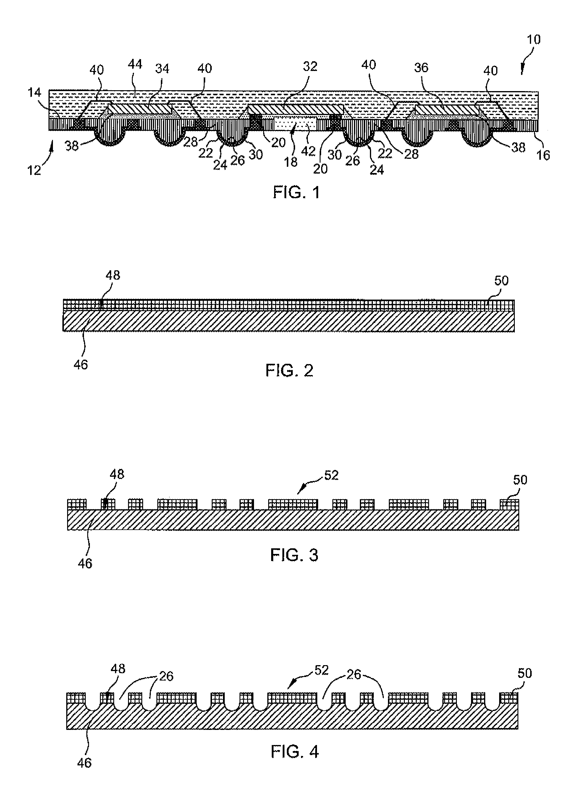
The present invention provides a more reliable and economical way to package semiconductor pressure sensor dies. The invention is a bumped chip carrier type pressure sensor device that uses a metal sheet with cavities and a photolithographic material applied to the metal sheet. The invention also includes a method for assembling the pressure sensor device and separating the assembled pressure sensor devices from adjacent devices. The technical effects of the invention include improved reliability, reduced reliability issues, and increased efficiency in packaging smaller integrated circuits.

Problems solved by technology

Moreover, existing pressure sensor packaging techniques are expensive and have certain reliability issues.

Method used


Image

  • Pressure sensor device having bump chip carrier (BCC)
  • Pressure sensor device having bump chip carrier (BCC)
  • Pressure sensor device having bump chip carrier (BCC)

Examples


Embodiment Construction

[0024]Detailed illustrative embodiments of the present invention are disclosed herein. However, specific structural and functional details disclosed herein are merely representative for purposes of describing example embodiments of the present invention. The present invention may be embodied in many alternate forms and should not be construed as limited to only the embodiments set forth herein. Further, the terminology used herein is for the purpose of describing particular embodiments only and is not intended to be limiting of example embodiments of the invention.

[0025]As used herein, the singular forms “a,”“an,” and “the,” are intended to include the plural forms as well, unless the context clearly indicates otherwise. It further will be understood that the terms “comprises,”“comprising,”“includes,” and / or “including,” specify the presence of stated features, steps, or components, but do not preclude the presence or addition of one or more other features, steps, or components. It ...


PUM


Abstract

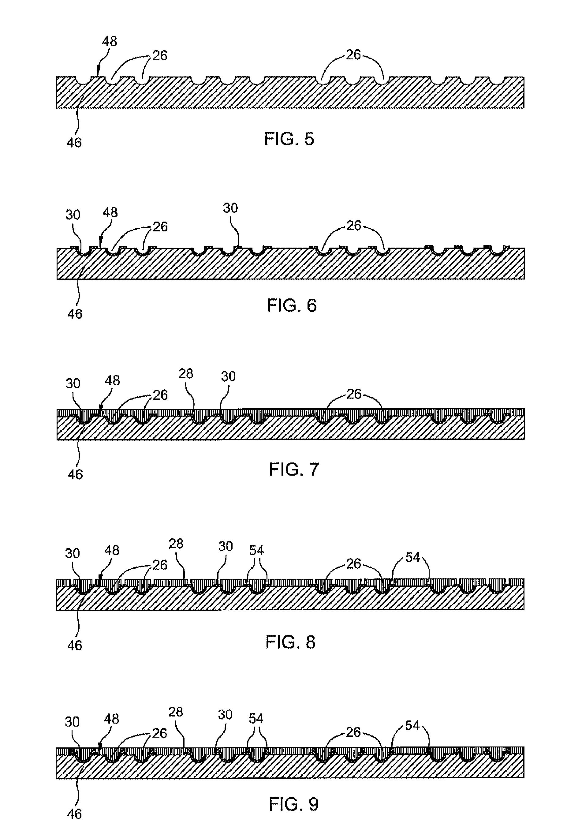
A pressure sensor device is assembled by forming cavities on a surface of a metal sheet and then forming an electrically conductive pattern having traces and bumps over the cavities. An insulating layer is formed on top of the pattern and then processed to form exposed areas and die attach areas on the surface of the metal sheet. The exposed areas are plated with a conductive metal and then electrically connected to respective ones of the bumps. A gel is dispensed on the die attach areas and sensor dies are attached to respective die attach areas. One or more additional semiconductor dies are attached to the insulating layer and bond pads of these dies are electrically connected to the exposed plated areas. A molding compound is dispensed such that it covers the sensor die and the additional dies. The metal sheet is removed to expose outer surfaces of the bumps.

Description

[0001]This application is a divisional of U.S. application Ser. No. 13 / 455,154 entitled “PRESSURE SENSOR DEVICE AND METHOD OF ASSEMBLING SAME” filed on Apr. 25, 2013 and assigned to the same assignee hereof.BACKGROUND OF THE INVENTION[0002]The present invention relates generally to pressure sensor devices, and more particularly to a bumped chip carrier type pressure sensor device.[0003]Modern electrical and electronic devices such as mobile phones, digital cameras and sensors require smaller and smaller integrated circuits. Packaging techniques have been developed to meet these requirements. Leaded bumped chip carrier (BCC) technology produces a chip scale lead frame based molded package with bumps, which are formed after the lead frame is etched away. However, existing BCC packages are peripheral non-pressure sensor wire bond types of packages. Moreover, existing pressure sensor packaging techniques are expensive and have certain reliability issues.[0004]Accordingly, it would be ad...

Claims


Application Information

Patent Timeline
Patent Type & Authority Patents(United States)
IPC IPC(8): H01L29/84H01L31/111H01L29/34H01L29/74H10N30/87
CPCH01L41/0475H01L23/3128G01L9/06H01L24/97H01L2224/73204H01L2224/92125H01L2924/181H01L2924/00H10N30/875
Inventor LO, WAI YEWLIM, FUI YEE
Owner NXP USA INC
Features
  • R&D
  • Intellectual Property
  • Life Sciences
  • Materials
  • Tech Scout
  • Unparalleled Data Quality
  • Higher Quality Content
  • 60% Fewer Hallucinations
Learn More