Magnetic suspension transducer

a transducer and magnetic suspension technology, applied in the field of acoustic transducers, can solve the problems of fatigue and wear, difficult manufacturing of soft parts, etc., and achieve the effect of reducing the reliance on flexible elements, and good low-frequency respons

Inactive Publication Date: 2015-01-27
TYMPHANY HK
View PDF5 Cites 18 Cited by
  • Summary
  • Abstract
  • Description
  • Claims
  • Application Information

AI Technical Summary

Benefits of technology

[0003]One object of the present invention is to eliminate or at least reduce the reliance on flexible elements in the construction of loudspeakers and headphones. Another object of the present invention is to provide good low-frequency response from an acoustic transducer that is compact in its physical dimensions.
[0005]According to one aspect of the present invention, an acoustic transducer includes a magnetic element and an electromagnetic element in proximity with the magnetic element. The magnetic element contains some permanently magnetic material and is located inside an apparatus such as a tube that restricts the relative motion between the magnetic element and the electromagnetic element to a path that is substantially a straight line. The magnetic element that is located inside the tube is referred to herein as an “internal magnetic element”. The tube may be constructed of any material that is non-magnetic, preferably non-conductive, durable, reasonably structurally rigid, reasonably resistant to heat, and either has a reasonably low coefficient of friction or is suitable for use with a lubricant that reduces friction between the tube and the internal magnetic element. For example, the tube may be constructed of glass or a plastic such as polyetheretherketon, polyetherimide, or fluoropolymer, or a glass-filled or mica-filled plastic. The electromagnetic element may be, for example, a wound coil attached to the outside or the inside of the tube that generates a signal-dependent magnetic field in response to an electrical signal. This signal-dependent magnetic field interacts with the magnetic field of the internal magnetic element, causing the internal magnetic element and the tube-coil assembly to vibrate relative to each other along the path essentially defined by the tube in response to varying electrical signals. A lubricant may be used inside the tube to reduce friction between the internal magnetic element and the tube and to reduce spurious noise generation. A ferromagnetic liquid is particularly suitable as a lubricant because it has low viscosity, it is partially held in its intended place around the internal magnetic element by the magnetic field of that element, and it acts to direct the magnetic force.
[0015]The tube-coil assembly may be composed of several components that are assembled using a process such as gluing or sonic welding to simplify the assembly procedure of the magnetic suspension transducer and to allow for the optimal design of each component. These components are preferably designed in a fashion that allows a close fit so that the overall structure has high rigidity and so that any lubricating fluid inside the tube is prevented from leaking. In a preferred embodiment, the central section of the tube nearest the coil is made from a non-conductive material to avoid reducing the effectiveness of the coil in undesirable ways such as through the induction of eddy currents in the material. The components located at some distance from the coil may generally be constructed of materials selected without regard to their conductivity.
[0020]In one embodiment of the present invention, the internal magnetic element is a cylindrical or annular slug made of a permanent magnetic material, such as Neodymium Iron Boron (NdFeB). In this embodiment, the one or more electromagnetic coils are preferably wound as close to the outer surface of the tube as possible. This reduces the gap between the one or more coils and the internal magnetic element and improves the efficiency of the magnetic circuit. The length of these one or more coils may be approximately equal to the length of the internal magnetic element. A ferromagnetic liquid may be used to form bearings that facilitate and stabilize the relative motion between the internal magnetic element and the tube-coil assembly. In a preferred embodiment, the ferromagnetic liquid is concentrated towards certain points on the internal magnetic element through the action of the magnetic field shape of the internal magnetic element.
[0021]In another embodiment of the present invention, the internal magnetic element has a structure similar to the motors of conventional transducers. For example, the internal magnetic element may be composed of a cylindrical or annular slug made of a permanent magnetic material, such as Neodymium Iron Boron (NdFeB), which is attached on one side to a cylindrical or annular slug made of a ferromagnetic material such as steel, and this composite two-piece slug is attached on the other side to a cylindrical or annular housing also made of a ferromagnetic material such as steel. The housing surrounds the slug made of a permanent magnetic material. The outer diameter of the slug made of a permanent magnetic material is slightly smaller than the inner diameter of the housing and the gap between them has an annular shape. The electromagnetic coil is attached to the inside of the tube and is normally positioned inside the annular gap between the outer diameter of the slug and the inner diameter of the housing. In this configuration, the magnetic field lines emanating from the permanent magnet are concentrated inside the ferromagnetic material of the top and bottom slugs and the housing. This implies that the magnetic field inside the annular gap is very strong and, therefore, the magnetic circuit is very efficient. A ferromagnetic liquid may be used as a lubricant inside the annular gap and around the ferromagnetic housing to facilitate and stabilize the motion of the tube-coil assembly relative to the internal magnetic element.

Problems solved by technology

Generally, the flexible elements in a loudspeaker or headphone are referred to as “soft parts.” These soft parts are difficult to manufacture and are subject to fatigue and wear.

Method used


Image

  • Magnetic suspension transducer
  • Magnetic suspension transducer
  • Magnetic suspension transducer

Examples


Embodiment Construction

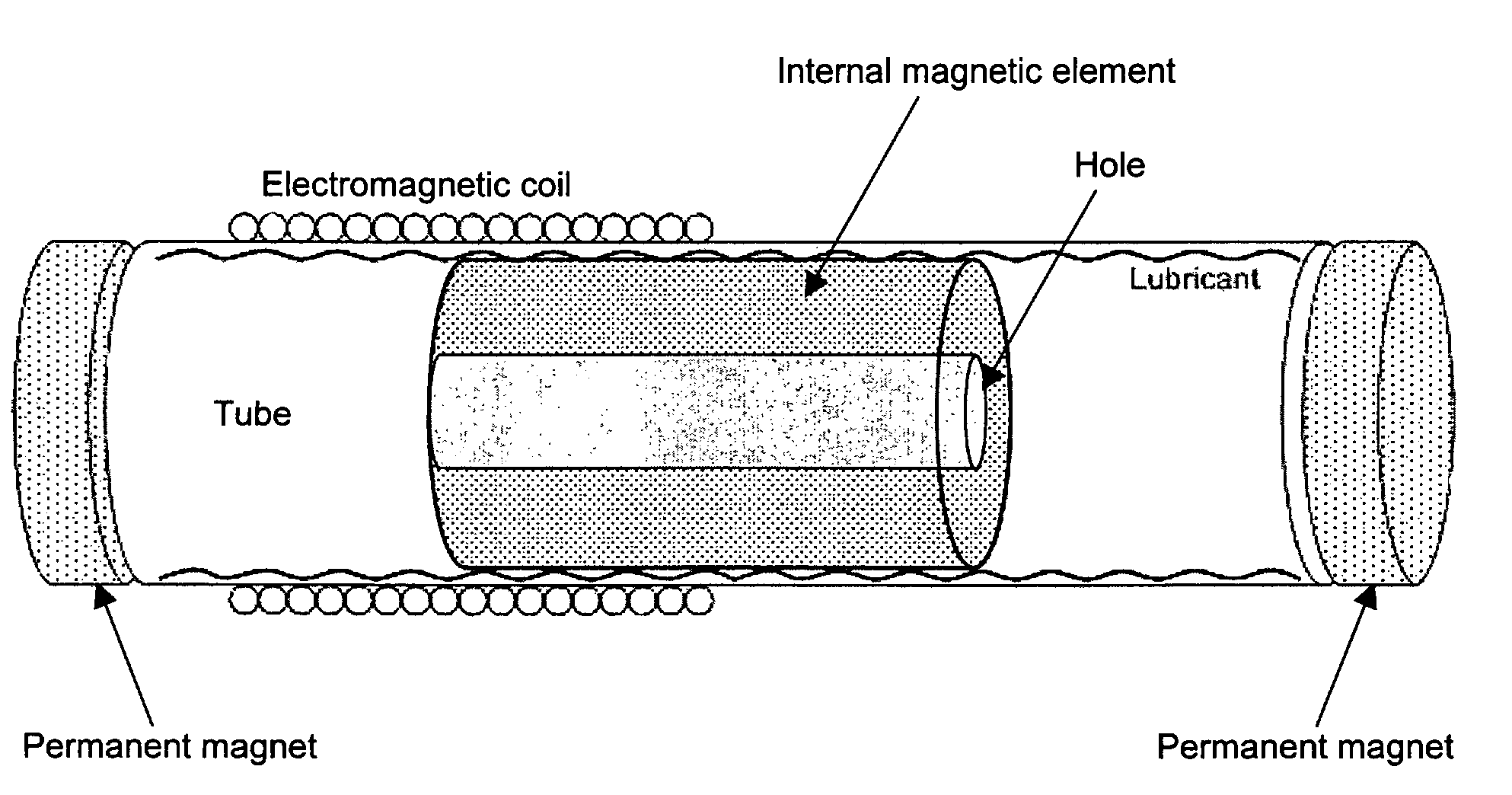
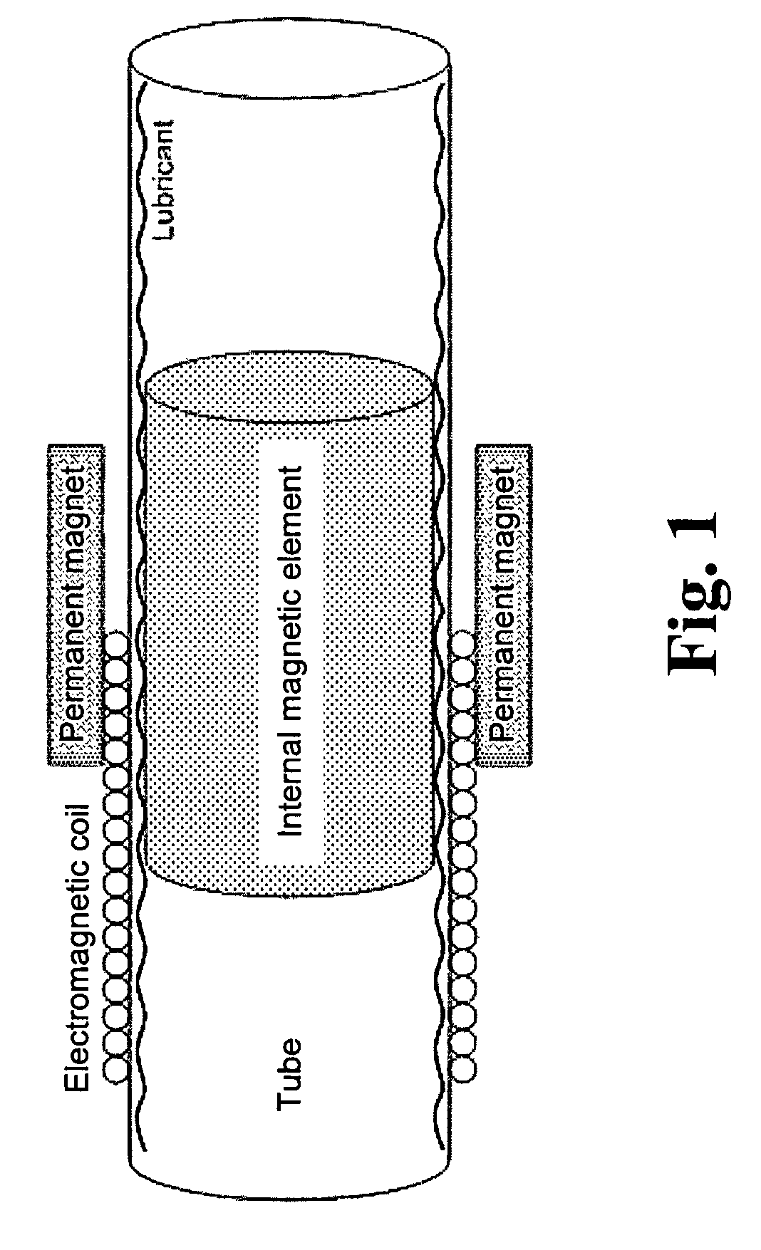
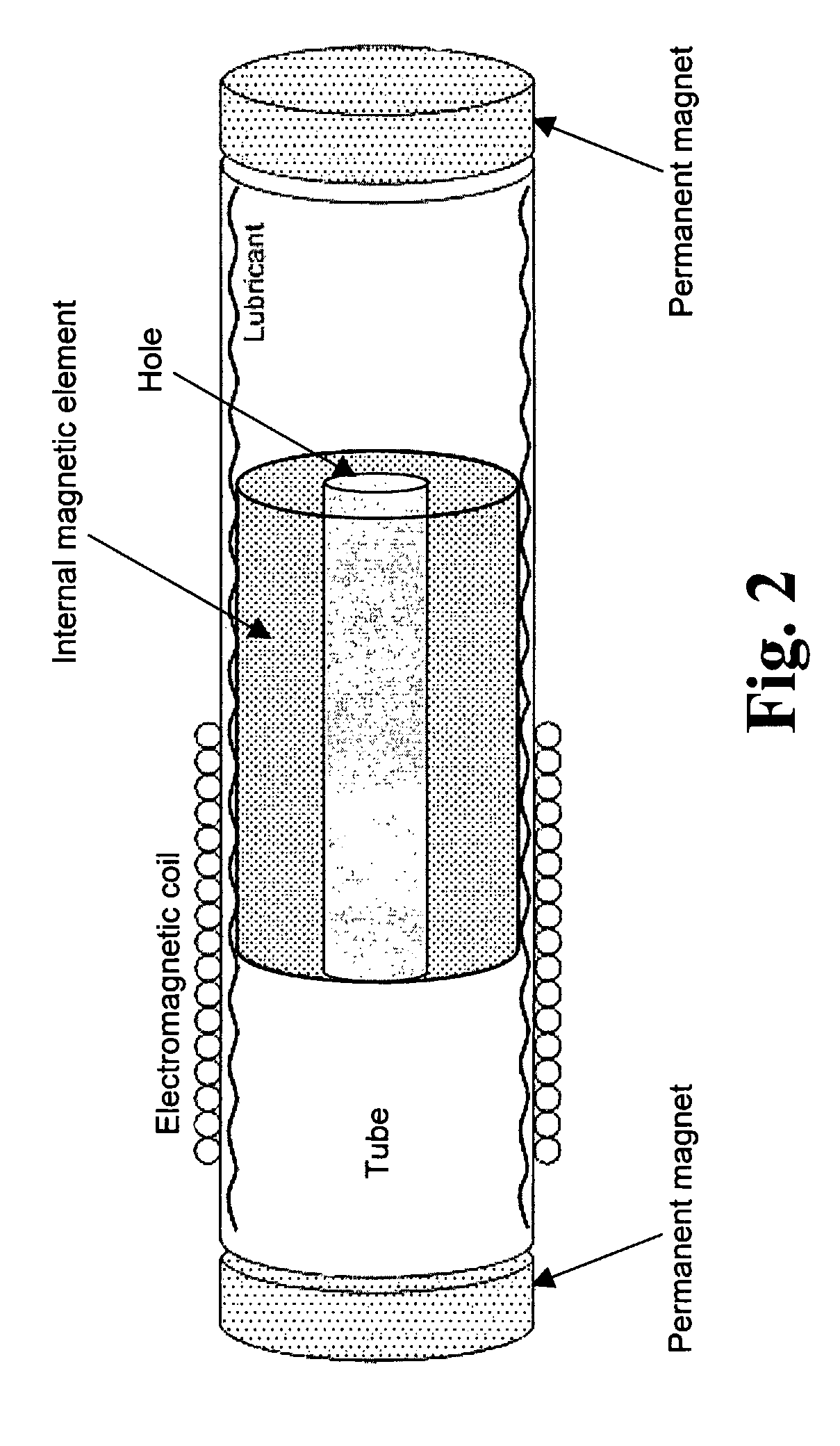
[0031]FIG. 1 shows one implementation of the present invention in which a tube supports an internal magnetic element such that it can move freely along the length of the tube. A restoring force is applied to the internal magnetic element by two permanent magnets with their centers at or near the midpoint of the tube, namely a location along the longitudinal axis of the tube that is equidistant from the ends of the tube. Preferably the two permanent magnets are positioned around the tube and oriented so that they apply a net restoring force to the internal magnetic element that is substantially parallel to the long axis of the tube. The restoring force attracts the internal magnetic element toward its nominal rest position, which in this implementation is at or near the point along the length of the tube that is equidistant from the ends of the tube. Preferably the magnetic field axes of the permanent magnets and the internal magnetic element are parallel to the long axis of the tube...


PUM


Abstract

An improved electrodynamic acoustic transducer eliminates or reduces the need for flexible or elastic materials to suspend an internal magnetic element by using both static and dynamic signal-dependent magnetic fields to control its movement. In one implementation, the transducer has a magnet that moves within a surrounding tube. This tube in turn supports one or more electromagnetic coils that generate a dynamic signal-dependent magnetic field that causes the internal magnetic element to vibrate. The surrounding tube also supports one or more magnets whose location on the tube is fixed and whose magnetic fields provide appropriate restoring forces acting on the internal magnetic element. These fixed magnets may be replaced or supplemented by ferromagnetic materials. This transducer may provide sound and infrasonic vibration by coupling the internal magnetic element to other radiating elements or by being placed in close proximity to or in actual contact with the pinna or meatus of the human ear when used in headphones or earphones, for example, and it also may provide sound through the direct vibration of the air in contact with the surface of the internal magnetic element. When direct atmospheric coupling is not required, the transducer may be assembled in a sealed enclosure.

Description

TECHNICAL FIELD[0001]The present invention pertains generally to acoustic transducers such as loudspeakers and headphones that may be constructed without the use of compliant, flexible or elastic materials.BACKGROUND ART[0002]Loudspeakers and headphones are devices that transform electrical signals into acoustic vibrations. This process requires that the loudspeaker or headphone contain moving parts that excite sound waves in the surrounding air either directly or indirectly through intermediate vibrating structures. These moving parts must be suspended in some manner that allows them to move over the distance and frequency range necessary to produce the desired sound output. Traditionally, flexible materials such as rubber and fabric are used to construct loudspeaker and headphone suspension systems. These flexible materials are used to interconnect those more rigid elements that move with respect to the loudspeaker or headphone housing. Generally, the flexible elements in a loudsp...

Claims


Application Information

Patent Timeline
Patent Type & Authority Patents(United States)
IPC IPC(8): H04R25/00H04R9/02H04R9/04H04R11/02
CPCH04R9/025H04R25/00H04R9/066H04R9/06H04R2209/041H04R1/00H04R11/02
Inventor KANTOR, KENNETH L.KANELLAKOPOULOS, IOANNISJABBARI, ALIREZA
Owner TYMPHANY HK
Why Eureka
Try Eureka