Humidification arrangement for a respiratory apparatus

a technology for respiratory apparatuses and humidifiers, applied in respirators, lighting and heating apparatuses, combustion types, etc., can solve the problems of reducing affecting the vaporisation rate of water, so as to increase the rate of vaporisation. the effect of water

Inactive Publication Date: 2015-02-03
RESMED LTD
View PDF21 Cites 5 Cited by
  • Summary
  • Abstract
  • Description
  • Claims
  • Application Information

AI Technical Summary

Benefits of technology

[0020]A further form of the invention provides a heater which is in thermal contact with the humidification apparatus. The heater may be used to increase the rate of vaporisation of the water within the humidification apparatus.

Problems solved by technology

However such a humidifier arrangement has a limited area of interaction between the surface of the water in the tub and the gas flowing above so that the capacity to deliver a high absolute humidity rapidly is limited.
In addition the humidified air may cool on its path along the conduit from the humidifier to the patient, leading to the phenomenon of “rain-out”, or condensation, forming on the inside of the conduit.
Tub-of-water humidifiers are also vulnerable to liquid water spillage if they are not maintained in the vertical.
In either of the cases the spillage of water is undesirable.
However such discrete humidification units have the disadvantages of being bulky to the patient and impeding the free movement of the gas conduit as the patient moves.
The disadvantage of such arrangements is the impediment to gas flow by the inserted tubes within the gas conduit to the patient.
The tubes may also contribute to the cleaning burden within the gas conduit.
However, the apparatus does not have the capacity to increase the absolute humidity beyond what can be gathered as a water source from the condensate in the gas conduit.
That is, the arrangement cannot increase the absolute humidity, merely restore it to the absolute humidity at which the gas is supplied to the conduit.
None of these prior art devices provides an entirely satisfactory solution to the provision of humidified breathable gas to the patient, nor to ease of construction and hygiene requirements for a humidification apparatus.

Method used


Image

  • Humidification arrangement for a respiratory apparatus
  • Humidification arrangement for a respiratory apparatus
  • Humidification arrangement for a respiratory apparatus

Examples


Embodiment Construction

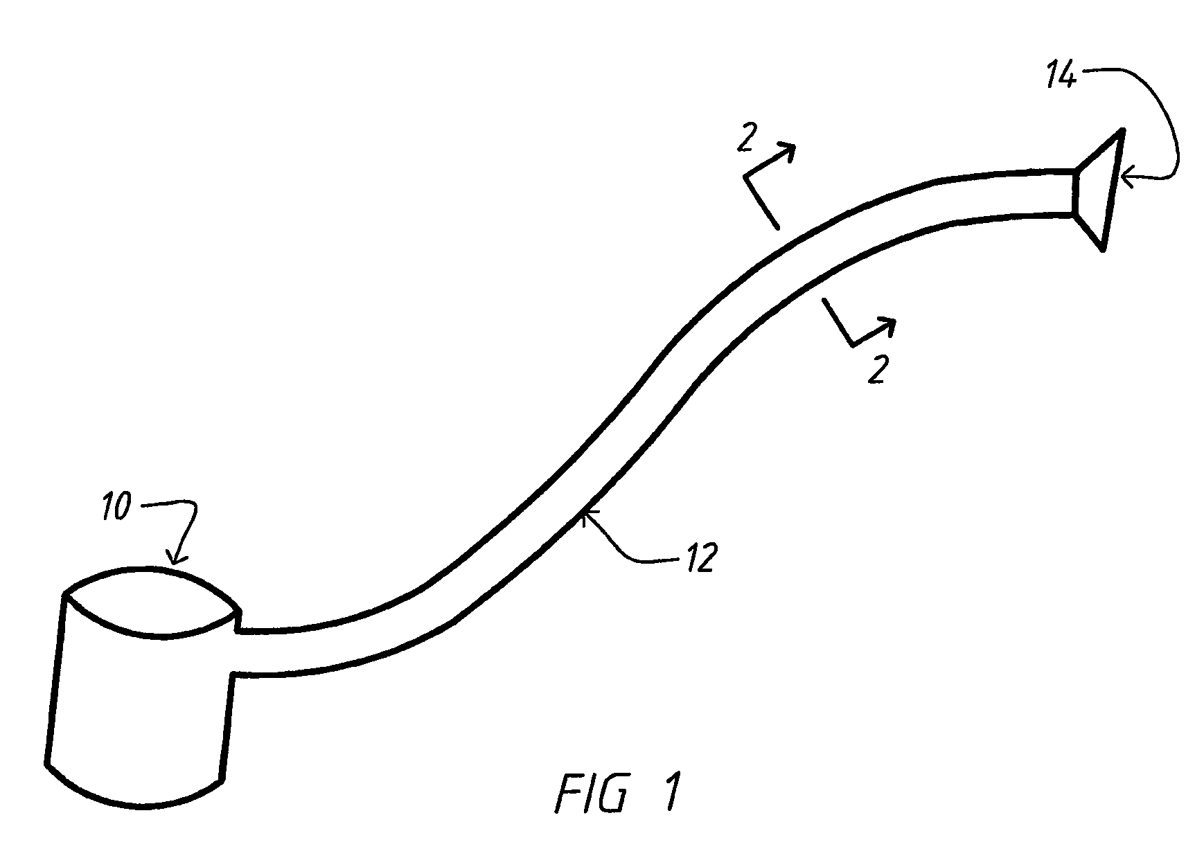
[0035]FIG. 1 schematically shows a PAP device 10 which produces a gas flow and gas pressure that is fed into a flexible conduit 12. The flexible gas conduit 12 has a central lumen 13 (FIG. 2) for conveying the gas flow to the patient mask 14 which is attached to the upper and / or lower airway of the patient or alternatively directly into the patient's airway via a tracheostomy tube. The humidifying apparatus of the present embodiments consists of the gas conduit 12 incorporating a humidification apparatus within it.

Semi-Permeable Membrane Portion

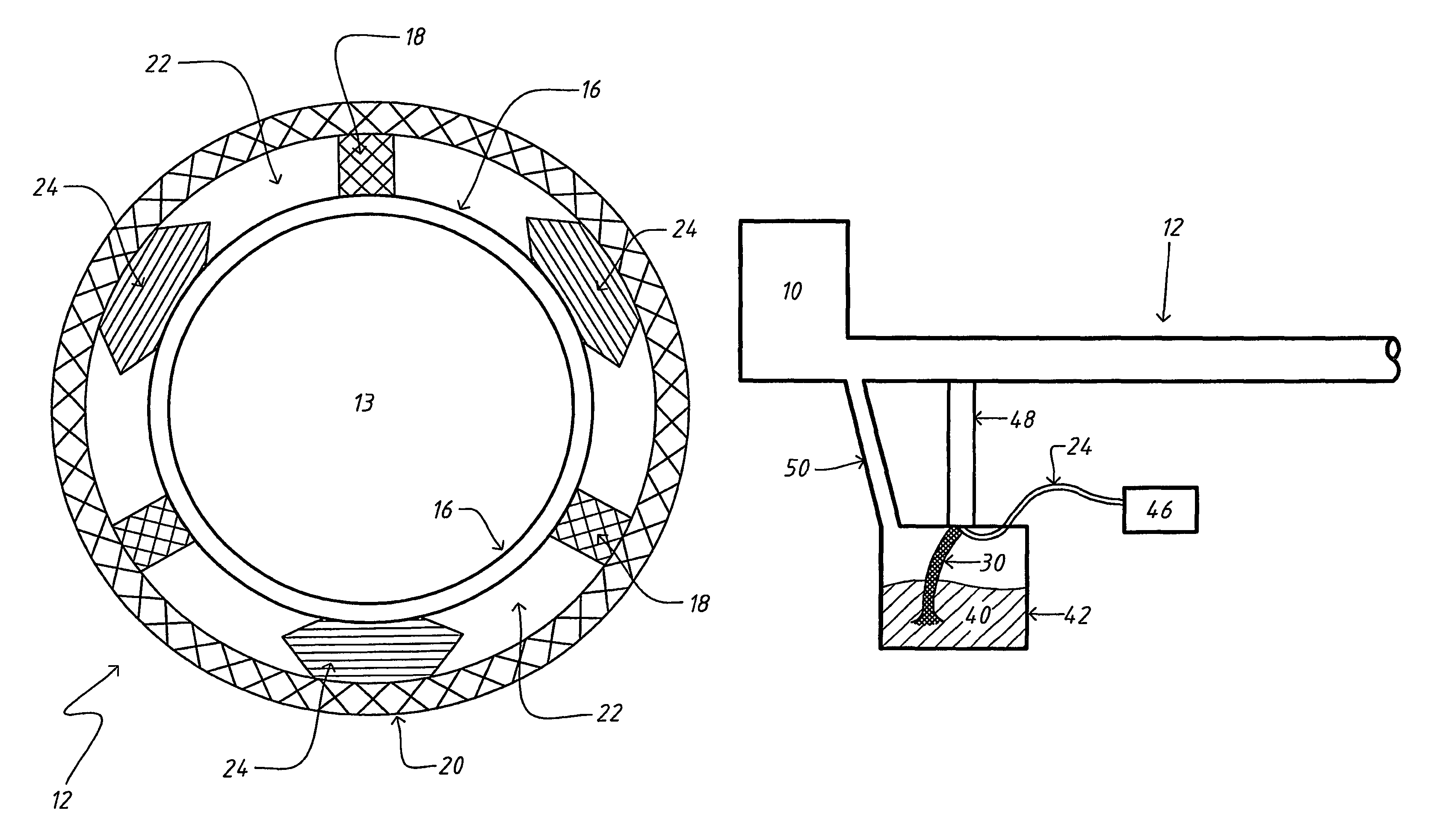
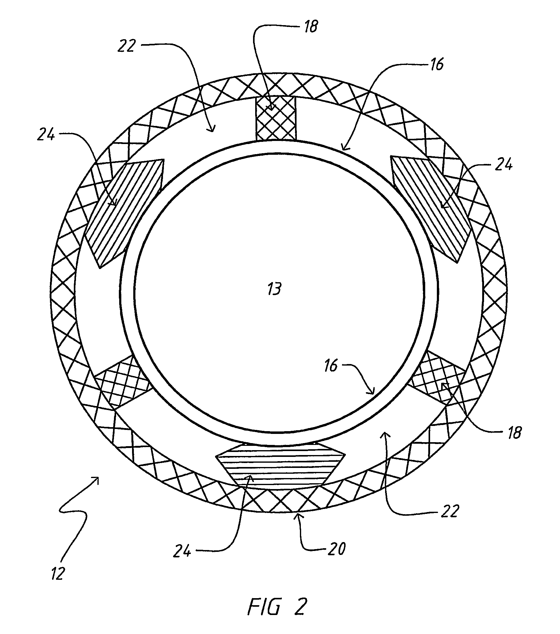
[0036]FIG. 2 illustrates a cross-sectional view of a humidification apparatus within a flexible gas conduit 12, according to a first embodiment. The humidification apparatus may have one or more semi-permeable membrane portions 16 which forms one or more portions of an inner wall of a double-walled conduit 12 and which allows water vapour to pass through the membrane but not liquid water. The inner wall of the double walled conduit 12 may be ...


PUM


Abstract

A humidifying apparatus utilizing a semi-permeable membrane portion within a gas conduit where the direction of gas flow within a central lumen is given by an arrow. The humidification apparatus has a helical configuration for the semi-permeable membrane portion, a structural reinforcing member or members, a water channel and a heating element. The helical configuration of an outer wall may be similar to conventional conduits that are in common use in respiratory apparatus. Thus the humidification apparatus may be readily substituted into existing respiratory device by exchanging the gas conduit.

Description

[0001]This application is the U.S. national phase of International Application No. PCT / AU2008 / 000145 filed 6 Feb. 2008, which designated the U.S. and claims priority to AU Application No. 2007900653 filed 9 Feb. 2007, the entire contents of each of which are hereby incorporated by reference.BACKGROUND OF THE INVENTION[0002]1. Field of the Invention[0003]The present invention relates to humidification arrangements used to control the humidity of breathable gases used in all forms of respiratory apparatus ventilation systems including invasive and non-invasive ventilation, Continuous Positive Airway Pressure (CPAP), Bilevel therapy and treatment for sleep disordered breathing (SDB) conditions such as Obstructive Sleep Apnea (OSA), and for various other respiratory disorders and diseases.[0004]2. Description of the Art[0005]Respiratory apparatus commonly have means to alter the humidity of the breathable gas in order to reduce drying of the patient's airway and consequent patient disco...

Claims


Application Information

Patent Timeline
Patent Type & Authority Patents(United States)
IPC IPC(8): A61M16/00A62B7/00F24J3/00F23D11/00H05B3/00A61M15/00F23D14/00A61M16/08A61M16/10A61M16/14A61M16/16
CPCA61M16/0875A61M16/1075A61M16/16A61M16/109A61M16/142A61M16/161A61M16/0003A61M16/06A61M16/0057A61M16/1095A61M2205/3368A61M2206/14A61M2205/3334A61M2016/003A61M16/162A61M16/1055A61M16/106
Inventor VIRR, ALEXANDERDARKIN, DONALDROW, NATHAN JOHNKLASEK, PAUL JAN
Owner RESMED LTD
Why Eureka
Try Eureka