
Bicycle parking apparatus

a technology for bicycles and parking apparatuses, applied in the direction of bicycle equipment, bicycle stands, dismountable cabinets, etc., can solve the problems of complicated and redundant work processing, and achieve the effect of effectively shortening the length of the second tubular sha

Inactive Publication Date: 2015-02-03
CHIU FU SHENG
View PDF49 Cites 1 Cited by
  • Summary
  • Abstract
  • Description
  • Claims
  • Application Information

AI Technical Summary

Benefits of technology

[0006]A primary object of the present invention is to provide an improved bicycle parking apparatus having a second tubular shaft, which, by the adjustment of the tubular shaft, can work to effectively reduce its volume, to minimize its storage volume.
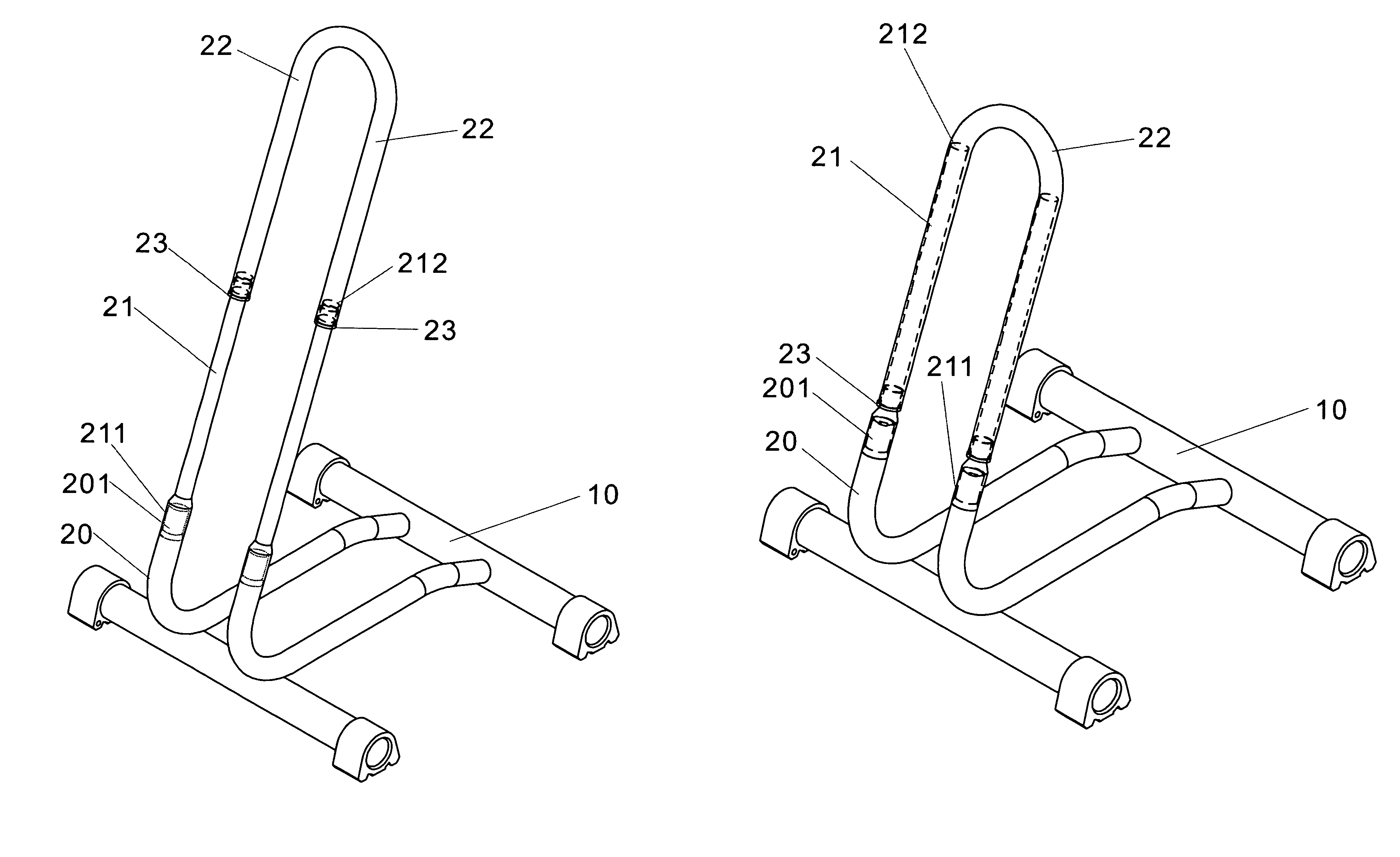
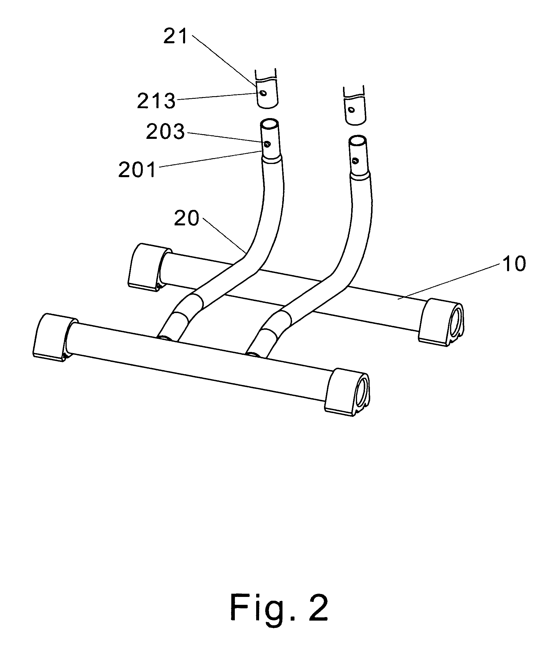
[0012]In another aspect of the present invention, the third tubular shaft has a second connector and a pin, which are involved in the assembly with the enfolding portion of the second tubular shaft; for the parking base, two parallel frames are welded or threaded to the third tubular shaft, when the parking base and the third tubular shaft are combined into a single device, the second tubular shaft works to insert into the second connector of the third tubular shaft. Due to the effect of an elastic device, the pin installed on the second connector can be attached in the pin locking member of the second tubular shaft, the second tubular shaft is retractable within the tubular shaft of the first tubular shaft, so that the length of the second tubular shaft can be effectively shortened to a manageable size for storage.

Problems solved by technology

A known disadvantage with this prior invention is the complicated and redundant work processing involved.

Method used


Image

  • Bicycle parking apparatus
  • Bicycle parking apparatus
  • Bicycle parking apparatus

Examples


Embodiment Construction

[0020]The following description, along with the drawings attached herewith showing a preferred embodiment of the present invention, is provided here for reference for the skilled persons related to the technical field of the present invention. Examples disclosed in the current written description are the following:

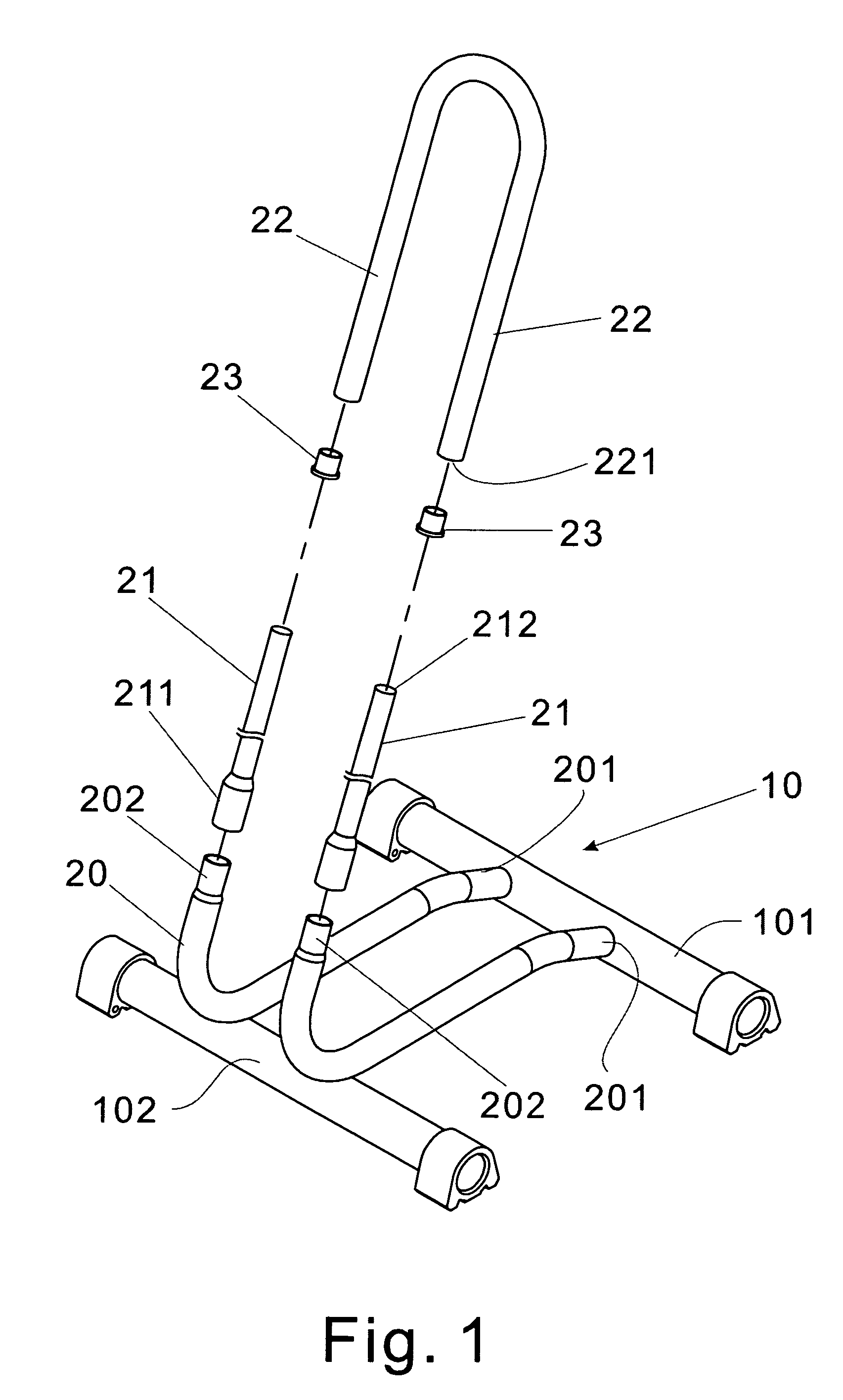
[0021]Referring now to FIG. 1, an improved bicycle parking apparatus of the present invention is disclosed, comprising: a parking base 10, a pair of third tubular shaft 20, a pair of second tubular shaft 21, and a pair of tubular shaft jacket 23; wherein, the parking base 10 is made of a first frame 101 and a second frame 102 assembled in a parallel arrangement, a pair of parallel third tubular shafts 20 is disposed in a perpendicular fashion between the first frame 101 and the second frame 102 by means of lock or welding, the third tubular shaft 20 has a first connector 201 and a second connector 202, the first connector 201 is welded onto the first frame 101, a side of t...


PUM


Abstract

An improved bicycle parking structure is disclosed, including a parking base having a third tubular shaft and a pair of second tubular shafts, a pair of tubular shaft jackets; featuring a first tubular shaft having a tubular space adapted for extensible and collapsible movement of a second tubular shaft, a tubular shaft jacket disposed underneath a tubular shaft opening of the first tubular shaft, wherein outer diameter of an end of the jacket is slightly larger than outer diameter of first tubular shaft, outer diameter of a connector of another end occurs to match inner diameter of tubular shaft opening. Said connector is coupled to the inner wall of the tubular shaft opening, so the second tubular shaft can be locked into an expanded portion of an end of the second tubular shaft when inserted into tubular shaft opening, to therefore effectively reduce second tubular shaft length for space conservation.

Description

BACKGROUND OF THE INVENTION[0001]1. Fields of the Invention[0002]The present invention relates to an improved bicycle parking apparatus, more particularly to an improvement for a bicycle parking apparatus adapted for adjusting the size of the apparatus to minimize its storage volume.[0003]2. Descriptions of Related Art[0004]It is known, for example as described in Taiwanese Patent TW1002244119 to provide a collapsible automobile frame structure, wherein an automobile frame structure is disclosed, comprising: a lower frame having a lower tank; a first tubular shaft that is adjustably attached onto a lower frame, the first tubular shaft has two sets of multiple-gear second tubular shafts located on an upper end of the first tubular shaft at an end of the first tubular shaft as connected by a connecting tubular shaft, so as to form a lateral frame tank between the two sets of multiple-gear second tubular shafts.[0005]A known disadvantage with this prior invention is the complicated and...

Claims


Application Information

Patent Timeline
Patent Type & Authority Patents(United States)
IPC IPC(8): A47F7/00A47B45/00A47F5/10A47F7/04B60R9/10B62H3/00B62H3/04B62H3/06
CPCB62H3/00A47B45/00A47F5/10A47F7/04B62H3/06B60R9/10B62H3/04
Inventor CHIU, FU-SHENG
Owner CHIU FU SHENG
Learn More