
Coaxial electrical connector and coaxial electrical connector device

a technology of coaxial electrical connectors and coaxial electrical connectors, which is applied in the direction of coupling device details, fixed connections, coupling device connections, etc., can solve the problems of connector damage, inability to smooth mating or removal operation, etc., and achieve the effect of reducing mounting errors, reducing the height of the connector, and improving production yield

Inactive Publication Date: 2015-02-03
DAIICHI SEIKO CO LTD
View PDF22 Cites 12 Cited by
  • Summary
  • Abstract
  • Description
  • Claims
  • Application Information

AI Technical Summary

Benefits of technology

[0008]It is an object of the present invention to provide a coaxial electrical connector and a coaxial electrical connector device configured so that the guiding function of an annular contact upon mating / removal of an opposing connector is maintained well with a simple configuration.
[0010]According to the coaxial electrical connector having such a configuration, the entire annular contact has an unruptured integrated structure. Therefore, compared with the conventional annular contact having the ruptured parts in the circumferential direction, rigidity is increased while maintaining necessary elasticity. For example, even when the opposing connector is mated or removed in a direction inclined in an axial direction with respect to the axial direction of the annular shape, conventional twisting deformation is suppressed in the annular contact. As a result, the mating guiding function of the annular contact is maintained well, and the opposing connector is therefore stably guided along the axial direction of the annular shape.
[0012]According to the coaxial electrical connector having such a configuration, upon mating / removal of the opposing connector, the opposing connector is smoothly moved along the curved surface provided at the annular opening of the annular contact, and the mating guiding function of the annular contact is further improved.
[0014]According to the coaxial electrical connector having such a configuration, stress generated in the annular contact upon mating / removal of the opposing connector is dispersed to the entire annular contact via the through holes, and usage durability of the annular contact is enhanced.
[0016]According to the coaxial electrical connector device having such a configuration, electrical connection of the signal contact is established at the center part of the ground contact. Therefore, positioning about the connection of the signal contact becomes unnecessary in the circumferential direction of the ground contact. As a result, even when the entire connector is rotated about the axis of the ground contact upon mounting to the wiring board, the mounting operation can be continued since there is almost no positional misalignment of the signal contact, mounting errors are reduced, and a so-called production yield is therefore improved. Moreover, since a member that insulates the upper side of the connection leg part of the signal contact like conventional cases becomes unnecessary, the height of the connector can be reduced, and the electromagnetic shielding characteristic (EMI characteristic) with respect to the signal transmission path is improved since an outer-peripheral-side part of the signal transmission path including the signal contact is covered with the ground contact.
[0017]As described above, the coaxial electrical connector and the coaxial electrical connector device according to the present invention increase rigidity while maintaining necessary elasticity compared with the conventional annular contact, which has the ruptured parts in the circumferential direction, by forming the annular contact by the unruptured annular member having no ruptured part in the circumferential direction and continued in the circumferential direction. For example when the opposing connector is mated or removed in a direction inclined in the axial direction with respect to the axial direction of the annular shape, twisting deformation in the annular contact is suppressed, and the opposing connector is stably guided along the axial direction of the annular shape so as to configure that the mating guiding function of the annular contact is maintained well. Therefore, the guiding function of the annular contact upon mating / removal with / from the opposing connector can be maintained well, and reliability of the coaxial electrical connector and the coaxial electrical connector device can be significantly enhanced with low cost.

Problems solved by technology

As a result, the mating guiding function of the annular contact with respect to the opposing connector is lowered, smooth mating or removing operation cannot be carried out, or connector damage is caused in some cases.

Method used


Image

  • Coaxial electrical connector and coaxial electrical connector device
  • Coaxial electrical connector and coaxial electrical connector device
  • Coaxial electrical connector and coaxial electrical connector device

Examples


Embodiment Construction

[0027]Hereinafter, an embodiment in which the present invention is applied to coaxial electrical connectors which mutually connect printed wiring boards and a coaxial electrical connector device will be explained in detail based on drawings.

[0028][About Overall Structure]

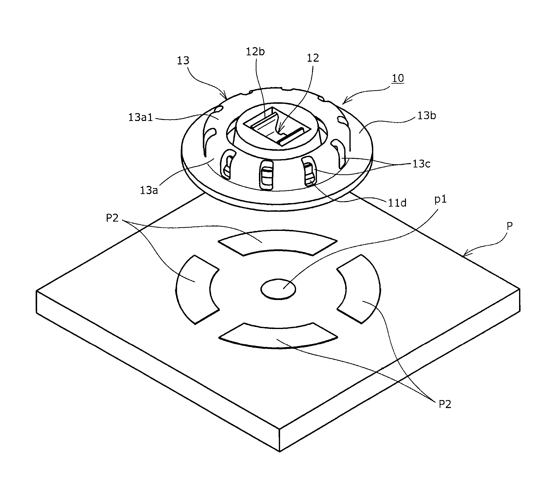
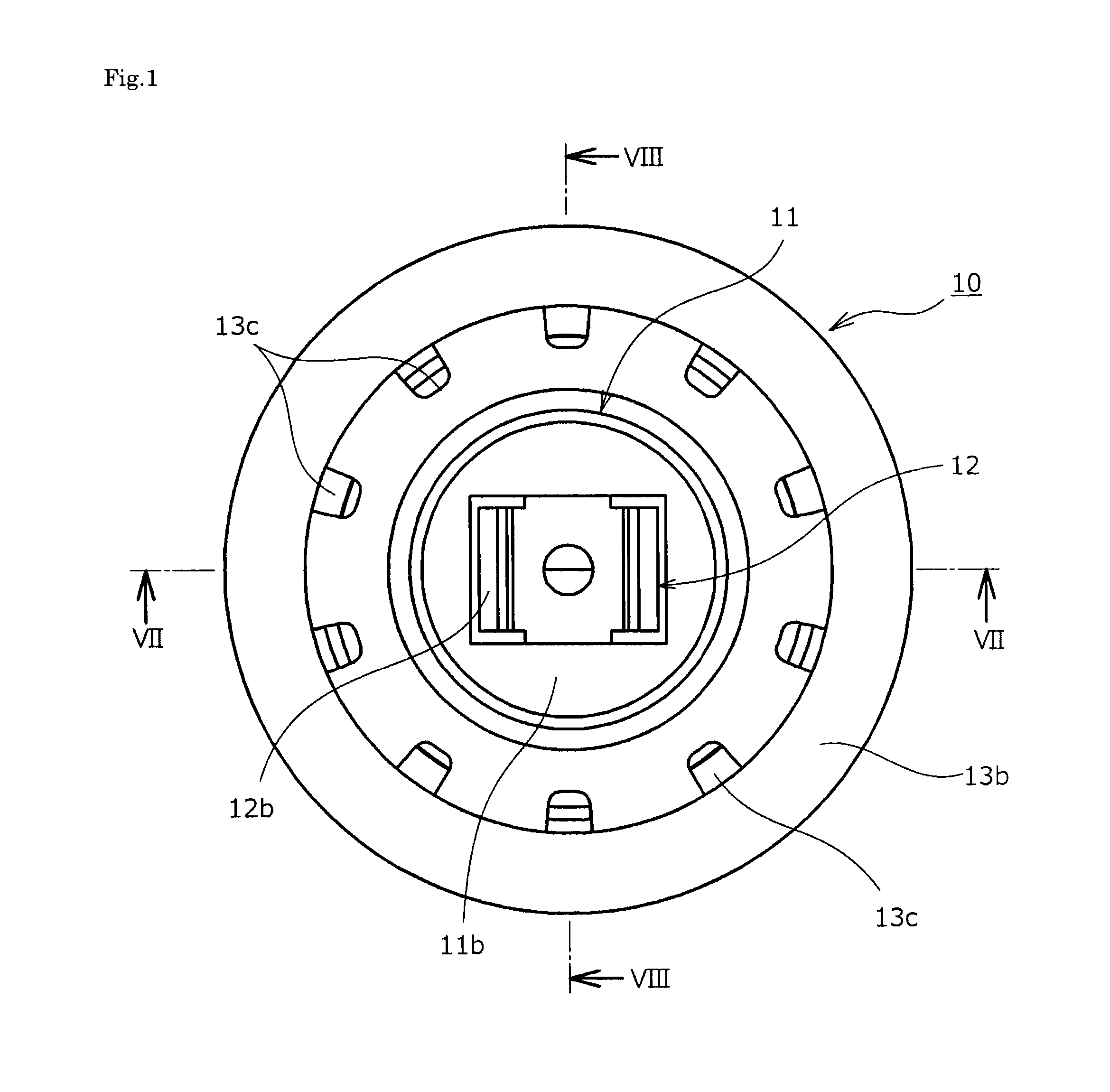
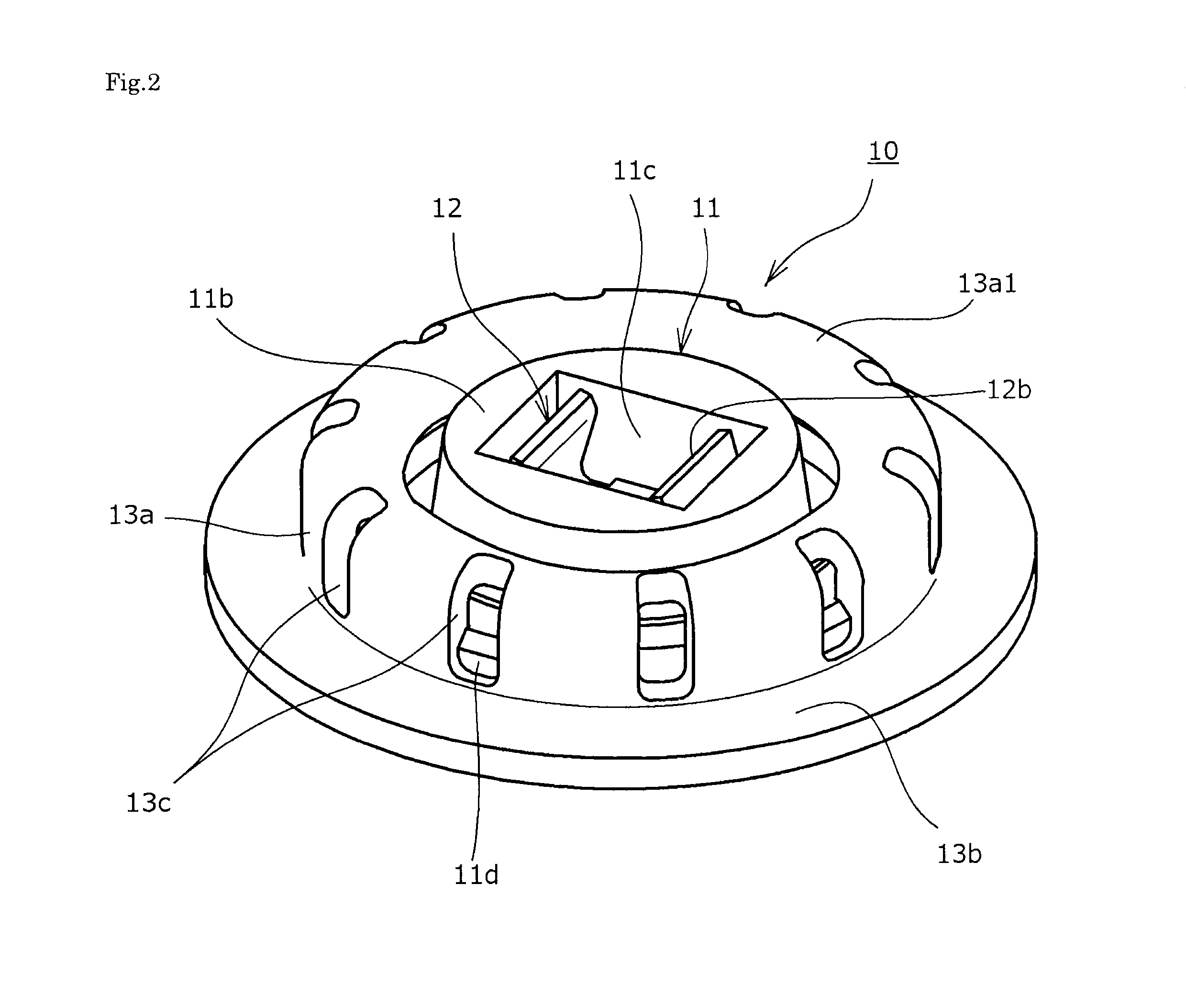
[0029]A coaxial electrical connector device using a coaxial electrical connector 10 according to an embodiment of the present invention shown in FIG. 1 to FIG. 9 is, for example, mounted by soldering on a printed wiring board P disposed on an electronic device such as a mobile phone, and, in the upper side of the coaxial electrical connector 10, another coaxial electrical connector 20 serving as an opposing connector is, for example, coaxially disposed while being held by a hand of an operator (see FIG. 5). When the coaxial electrical connector 20 is thrust in toward the coaxial electrical connector 10 therebelow with appropriate force, both of the connectors 10 and 20 are caused to be in a mutually mated state. Whe...


PUM


Abstract

A guiding function of an annular contact upon mating / removal with / from an opposing connector can be maintained well with a simple configuration. An annular contact is formed with an unruptured annular member having no ruptured part in a circumferential direction and continued in the circumferential direction. As a result, compared with a conventional annular contact having ruptured parts in the circumferential direction, rigidity is increased while maintaining necessary elasticity; and, for example even when an opposing connector is mated or removed in a direction inclined in an axial direction with respect to the axial direction of the annular shape, conventional twisting deformation is suppressed in the annular contact, and the opposing connector is stably guided along the axial direction of the annular shape, thereby well maintaining a mating guiding function of the annular contact.

Description

BACKGROUND OF THE INVENTION[0001]1. Field of the Invention[0002]The present invention relates to a coaxial electrical connector and a coaxial electrical connector device in which an annular contact, which is formed to have an annular shape, is configured to be elastically displaced via slits upon mating of an opposing connector.[0003]2. Description of Related Art[0004]Generally, in various electric devices, electrically connecting various signal transmission media such as thin coaxial cables and flexible wiring boards to printed wiring boards or electrically connecting a pair of wiring boards to each other (board to board) by using a pair of electrical connectors, which are configured to be able to be mated and connected with each other, has been widely carried out. As the pair of electrical connector as described above, for example, a plug connector (first connector), to which a signal transmission medium or a wiring board is coupled, and a receptacle connector (second connector), ...

Claims


Application Information

Patent Timeline
Patent Type & Authority Patents(United States)
IPC IPC(8): H01R12/00H01R12/57H01R12/70H01R13/60H01R24/50H01R103/00
CPCH01R13/60H01R12/57H01R24/50H01R2103/00H01R12/7082H01R9/05
Inventor OHSAKA, JUNJI
Owner DAIICHI SEIKO CO LTD
Learn More