
Method and apparatus for effective utilization of energy storage components within a microgid

a technology of energy storage components and micro-gids, applied in the energy industry, electric power transfer ac networks, transportation and packaging, etc., can solve the problems of overcharging or overdischarging of devices, premature wear and system failure, component capacity fade, etc., and achieve the effect of effective utilization of energy storage components

Active Publication Date: 2015-02-03
HONEYWELL INT INC
View PDF18 Cites 17 Cited by
  • Summary
  • Abstract
  • Description
  • Claims
  • Application Information

AI Technical Summary

Benefits of technology

This approach allows for precise state of charge and health monitoring, extending the operational life of energy storage components, preventing premature failure, and enabling efficient energy management within microgrids.

Problems solved by technology

The terminal voltage, particularly in the dynamic charge / discharge environment of the electric grid, is not a true indicator of storage component state of charge and can result in overcharge or overdischarge of the device.
Further, the component capacity fades with time and, if the component utilization is not based upon its current capacity, premature wear and system failure can result.

Method used


Image

  • Method and apparatus for effective utilization of energy storage components within a microgid
  • Method and apparatus for effective utilization of energy storage components within a microgid
  • Method and apparatus for effective utilization of energy storage components within a microgid

Examples


Embodiment Construction

[0012]The following detailed description is of the best currently contemplated modes of carrying out exemplary embodiments of the invention. The description is not to be taken in a limiting sense, but is made merely for the purpose of illustrating the general principles of the invention, since the scope of the invention is best defined by the appended claims.

[0013]Various inventive features are described below that can each be used independently of one another or in combination with other features.

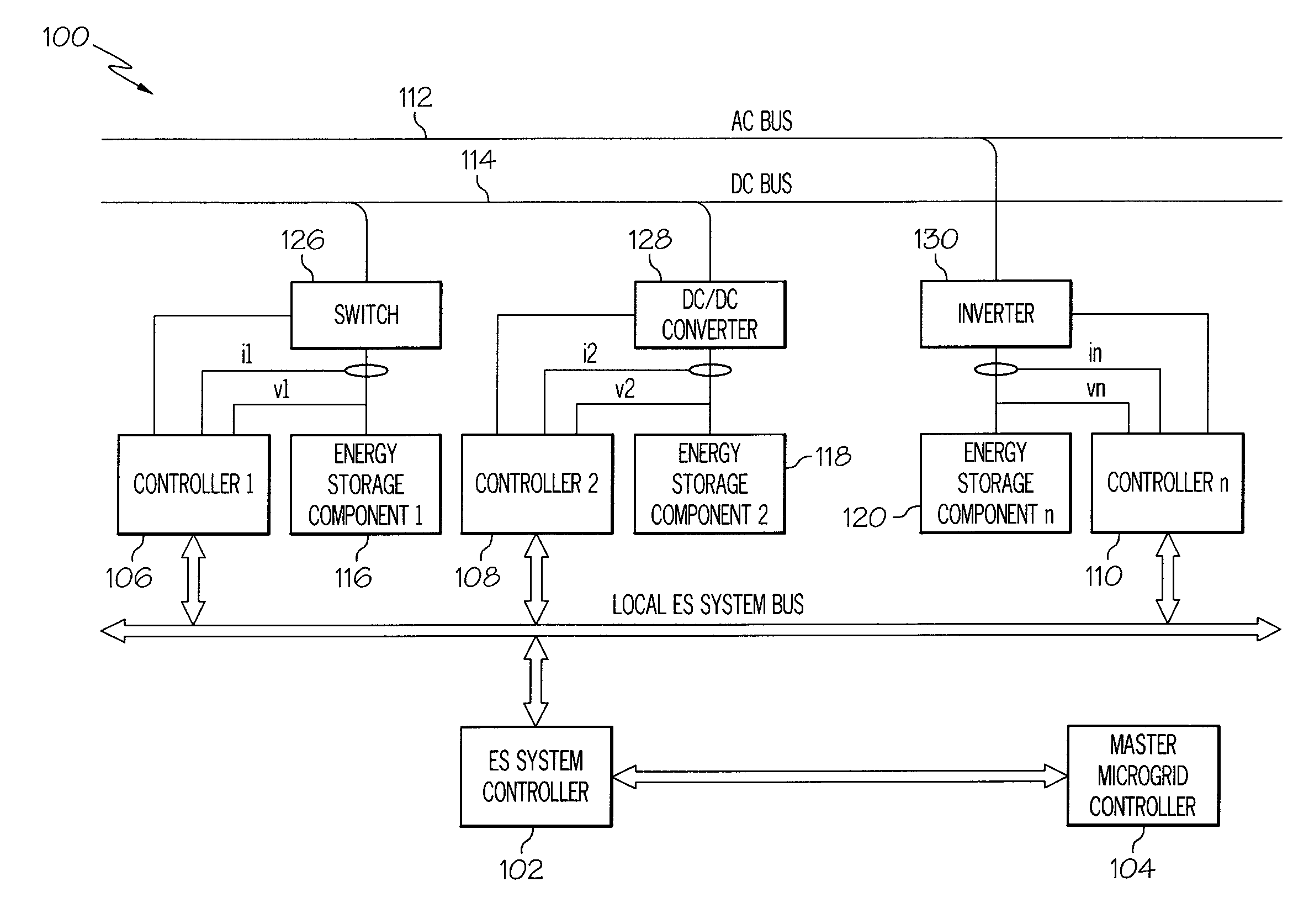
[0014]Broadly, embodiments of the present invention provide an online method and apparatus for determining state of charge (SoC) and state of health (SoH) of energy storage components in a microgrid environment The SoC and SoH can be determined from the energy storage component's voltage, charge or discharge current and temperature.

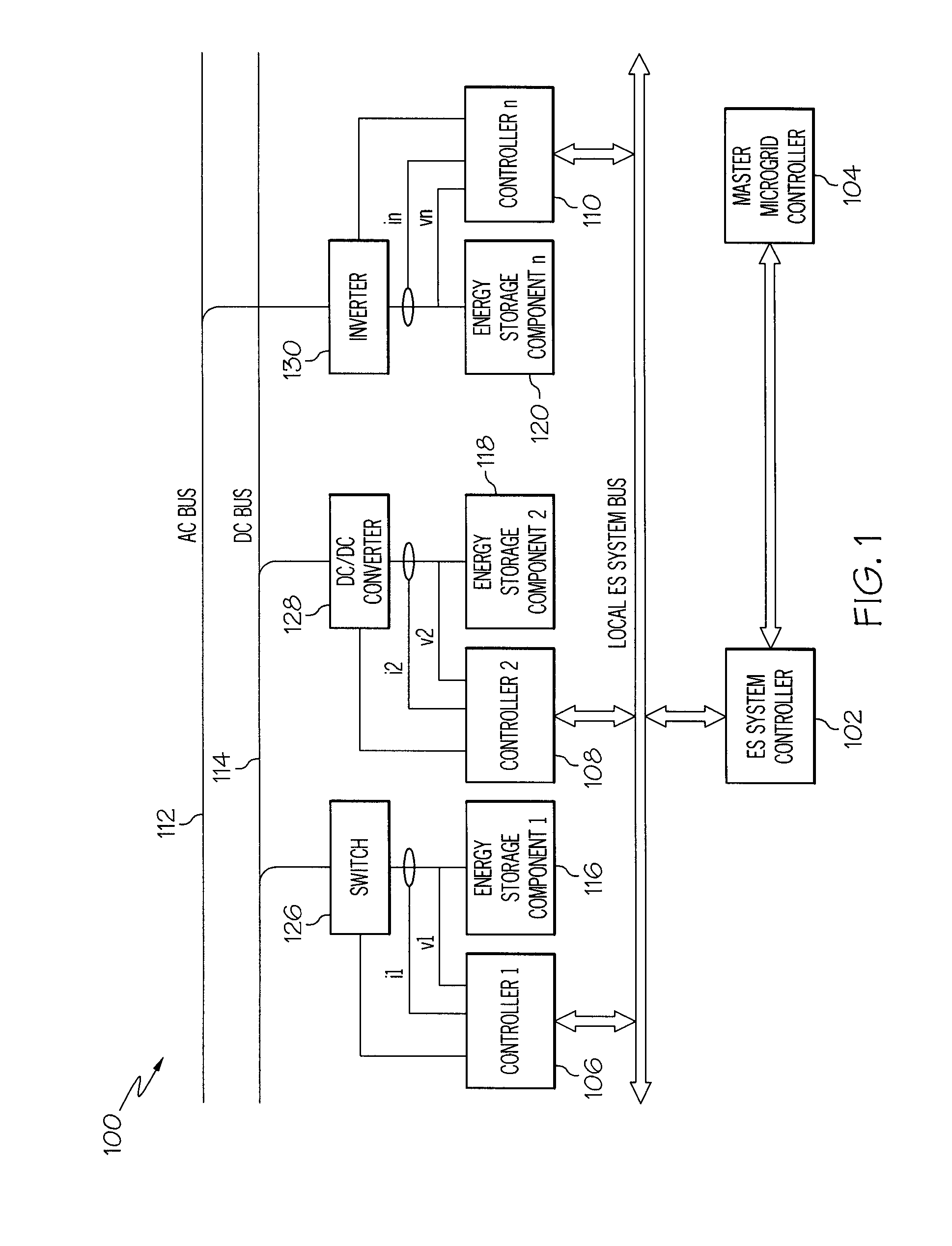
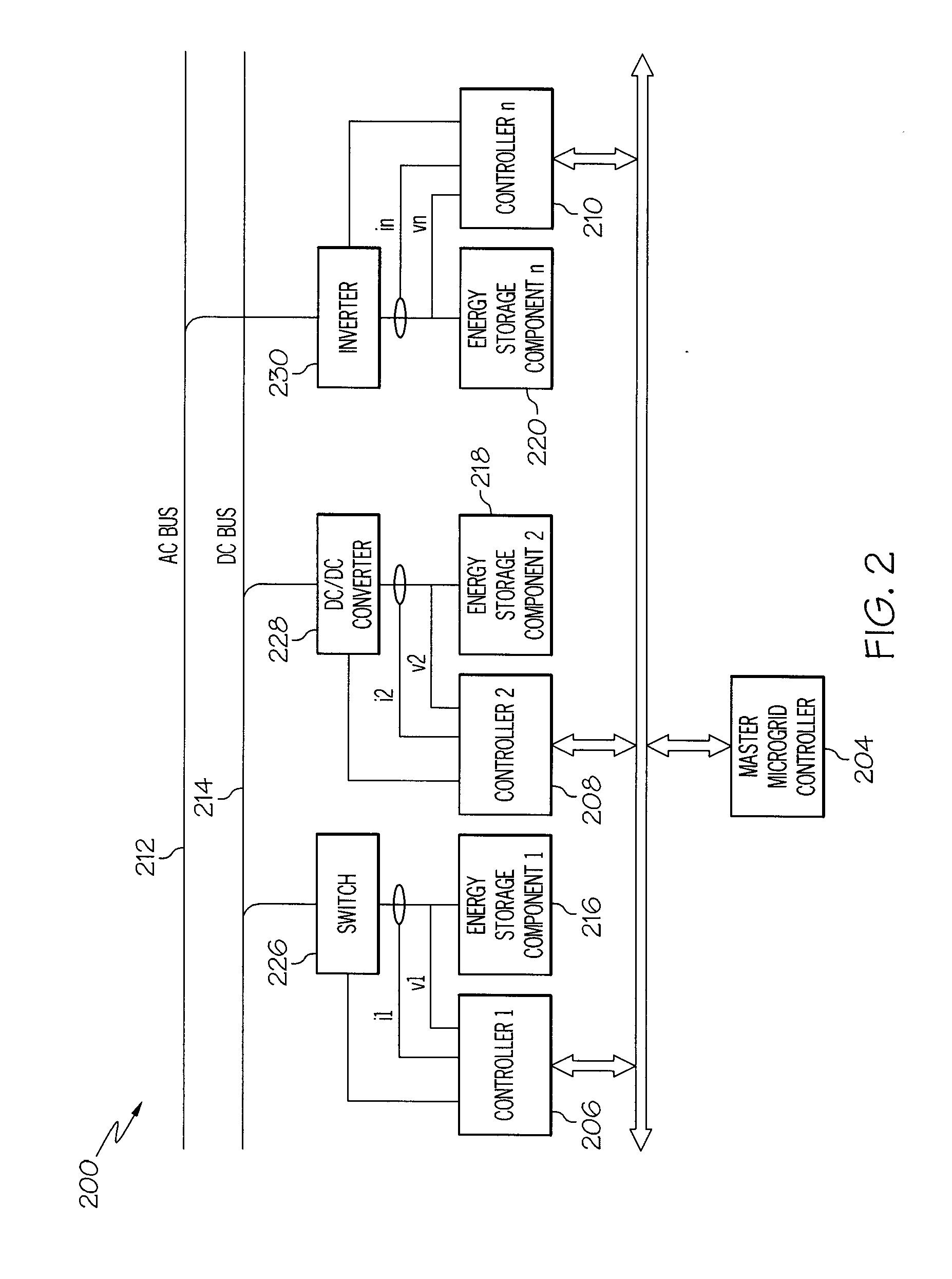
[0015]Referring to FIGS. 1 and 2, there are shown microgrid energy storage component management systems 100, 200 according to an exemplary embodiment of the pre...


PUM


Abstract

A method for effectively utilizing energy storage components within a microgrid may include the steps of connecting a first plurality of energy storage components to a DC bus through switches, connecting a second plurality of energy storage components to an AC bus through inverters, connecting controllers to the energy storage components, connecting a first plurality of the controllers to the DC bus to regulate bidirectional flow of energy between the DC bus and the first plurality of energy storage components and connecting a second plurality of the controllers to the AC bus to regulate bidirectional flow of energy between the AC bus and the second plurality of energy storage components. The controllers may be interconnected with a local energy storage system bus and controlled via a master microgrid controller connected to the local energy storage system bus. The controllers may have a state of charge and a state of health algorithm adapted to measure the state of charge and the state of health of the energy storage components under dynamic charge or discharge conditions.

Description

BACKGROUND OF THE INVENTION[0001]The present invention relates to apparatus and methods for energy storage and, more particularly, apparatus and methods for permitting in-situ determination and utilization of the state of charge and state of health of storage components in a microgrid.[0002]Microgrids are rapidly expanding as part of the effort to reduce dependence on fossil fuels and to increase the efficiency of generating electric energy. The microgrids typically consist of power generators, renewable energy sources and energy storage components. For energy storage, components such as rechargeable batteries, super-capacitors, fuel-cells, and the like, are used. One of the main objectives of the microgrids is to effectively use the electric storage to maintain line voltage regulation which can mainly occur due to the unpredictable duty cycles of the renewables. In order to lower the mass, volume and cost of each energy storage components and for microgrid life cycle cost reduction...

Claims


Application Information

Patent Timeline
Patent Type & Authority Patents(United States)
IPC IPC(8): H02J3/28H02J1/14H02J3/32H02J3/38H02J4/00
CPCH02J3/32H02J1/14H02J3/28H02J4/00H02J3/387Y02P80/14H02J2310/10H02J2300/30H02J3/381
Inventor SINGH, HARMOHAN N.ANGHEL, CRISTIAN
Owner HONEYWELL INT INC
Learn More