Power feeding system and vehicle

a technology of power feeding system and power supply device, which is applied in the direction of propulsion using engine-driven generators, electric devices, rail devices, etc., can solve the problems of power supply device and power feeding efficiency, and achieve the effect of simple structure and efficient power feeding

Active Publication Date: 2015-02-03
TOYOTA JIDOSHA KK
View PDF16 Cites 5 Cited by
  • Summary
  • Abstract
  • Description
  • Claims
  • Application Information

AI Technical Summary

Benefits of technology

[0011]The invention provides a power feeding system and a vehicle using the resonance method, each enabling efficient power feeding but being simple in structure.
[0014]Further, the power feeding system according to the first aspect of the invention may be such that the controller controls the impedance matching device based on the detected value of the reflected power, which has been received by the second communication device, so as to reduce the reflected power at the power supply device.
[0022]Further, the vehicle according to the second aspect of the invention may be such that the controller controls the impedance matching device based on the detected value of the reflected power, which has been received by the communication device, so as to reduce the reflected power at the power supply device.
[0027]According to the power feeding system according to the first aspect of the invention and the vehicle according to the second aspect of the invention, the power information on power at the power feeding installation is sent from the power feeding installation to the power receiving unit (e.g., the vehicle), and the power receiving unit (e.g., the vehicle) has the impedance matching device that adjusts the impedance at the resonance system that is constituted of the power transmission resonator and the power receiving resonator, and the impedance matching device is controlled based on the power information received from the power feeding installation. Thus, the resonance system impedance adjustment is performed only at the power receiving unit (e.g., the vehicle). According to the power feeding system and vehicle of the invention, thus, it is possible to achieve efficient power feeding using the resonance method with a simple structure.

Problems solved by technology

If these impedances are not matched to each other, the power reflected to the power supply device becomes large, and thus the power feeding is not efficient.

Method used


Image

  • Power feeding system and vehicle
  • Power feeding system and vehicle
  • Power feeding system and vehicle

Examples


Embodiment Construction

[0036]Hereinafter, example embodiments of the invention will be described in detail with reference to the drawings. Note that identical and corresponding elements in the drawings are denoted by identical reference numerals, and the descriptions on them will not be repeated.

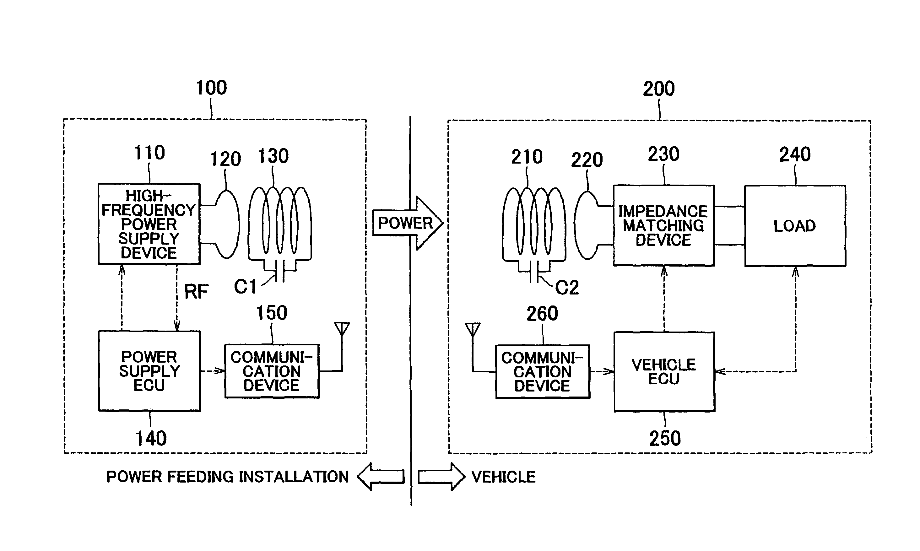
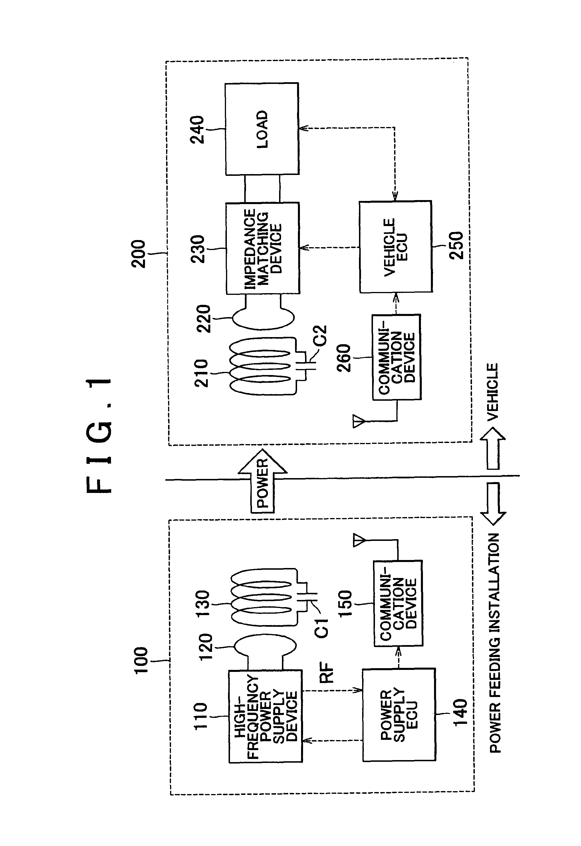
[0037]FIG. 1 is a view showing the entire structure of a power feeding system of the first example embodiment of the invention. Referring to FIG. 1, the power feeding system includes a power feeding installation 100 and a vehicle 200. The power feeding installation 100 has a high-frequency power supply device 110, a primary coil 120, a primary self-resonant coil 130, a power supply electronic control unit (ECU) 140, and a communication device 150.

[0038]The high-frequency power supply device 110 produces power having a predetermined frequency and supplies the power to the primary coil 120. The power produced by the high-frequency power supply device 110 is the high-frequency power for contactless, or wireless, powe...


PUM

PropertyMeasurementUnit
frequencyaaaaaaaaaa
frequencyaaaaaaaaaa
poweraaaaaaaaaa

Abstract

A power feeding system is provided, in which a detected value of reflected power at a power supply device in a power feeding installation is sent from the power feeding installation to a vehicle via a first communication device, the vehicle has an impedance matching device for adjusting an impedance at a resonance system that is constituted of a power transmission resonator, including a primary self-resonant coil and a primary coil in the power feeding installation, and a power receiving resonator, including a secondary self-resonant coil and a secondary coil in the vehicle, and the impedance matching device is controlled based on the detected value of the reflected power at the power supply device, which has been received from the power feeding installation.

Description

BACKGROUND OF THE INVENTION[0001]1. Field of the Invention[0002]The invention relates to a power feeding system and a vehicle, and the invention particularly relates to a power feeding system in which power is wirelessly fed from a power feeding installation to a vehicle by a power transmission resonator provided in the power feeding installation and a power receiving resonator provided in the vehicle resonating with each other via an electromagnetic field, and relates to a vehicle.[0003]2. Description of the Related Art[0004]Great attention has been focused on electrically powered vehicles, such as electric vehicles and hybrid vehicles, as environment-friendly vehicles. These vehicles incorporate an electric motor for producing drive force to propel the vehicle, and a rechargeable power storage for storing power to be supplied to the electric motor. Note that “hybrid vehicles” refer to vehicles incorporating an internal combustion engine as a motive power source in addition to the ...

Claims


Application Information

Patent Timeline
Patent Type & Authority Patents(United States)
IPC IPC(8): H01M10/46B60L5/00B60K6/445B60L11/18B60L50/15B60L50/16B60M7/00H02J5/00H02J7/00
CPCB60L11/182B60K6/445B60L11/123B60L11/14B60L11/1838H02J5/005Y02T90/16Y02T90/163B60L2220/14Y02T10/6217Y02T10/6239Y02T10/7005Y02T10/7077Y02T10/7088Y02T90/122Y02T90/128Y02T90/14Y02T10/7072B60L50/61B60L50/16B60L53/122Y02T10/62Y02T10/70Y02T90/12H02J50/80H02J50/12B60L53/12
Inventor ICHIKAWA, SHINJINAKAMURA, TORUTAKADA, KAZUYOSHISUZUKI, SADANORISAKODA, SHIMPEIYAMAMOTO, YUKIHIRO
Owner TOYOTA JIDOSHA KK
Why Eureka
Try Eureka