Radial-free collinear omni-directional antenna with gain and virtual ground

a collinear omni-directional antenna, gain technology, applied in the direction of antennas, elongated active element feeds, electrically short antennas, etc., can solve the problems of reducing the robustness of the antenna design, reducing the return effectively, and damage from being walked on, etc., to achieve low cost, low weight, and easy mass production

Inactive Publication Date: 2015-02-03
FONG EDISON
View PDF4 Cites 2 Cited by
  • Summary
  • Abstract
  • Description
  • Claims
  • Application Information

AI Technical Summary

Benefits of technology

[0024]The resultant antenna is omni-directional, is collinear, requires neither a ground plane nor radials, requires no an absolute RF ground, and exhibits gain relative to a half-wave dipole antenna. The antenna may be fabricated from an approximately 1.75 wavelength (at frequency of interest) piece of twinlead, with gaps or notches formed in the first lead at the appropriate locations. The antenna is readily mass producible at low cost, has low weight and is readily shippable, and is robust in that it is of integral one-piece construction.

Problems solved by technology

Further, radials diminish robustness of the antenna design, especially in inclement weather.
However a point of diminishing returns effectively occurs at about four elements in that marginal further increase in gain does not warrant the cost of the additional elements.
If the radials are on the ground, they may be damaged from being walked upon.
Further, the electrical conductivity between the radials and the shield of coaxial cable 60 will inevitably deteriorate over time.
However the sleeve configuration can make it difficult to achieve desired low SWR due to inherent coupling between the outer shield conductor of coaxial cable 60 and the wall of sleeve 150.
Ideally the phase delay and radiation patterns associated with element 200 are perfectly out-of-phase, but in practice some phase error and associated antenna inefficiency will exist.
However such solutions are not optimum because losses and tolerance changes in the L and C components vary over time, which can reduce effectiveness of the desired delay function.
With radials bent downward from say 0° (i.e., horizontal) to about 45°, and disadvantageously a relatively high angle of radiation will result.

Method used


Image

  • Radial-free collinear omni-directional antenna with gain and virtual ground
  • Radial-free collinear omni-directional antenna with gain and virtual ground
  • Radial-free collinear omni-directional antenna with gain and virtual ground

Examples


Embodiment Construction

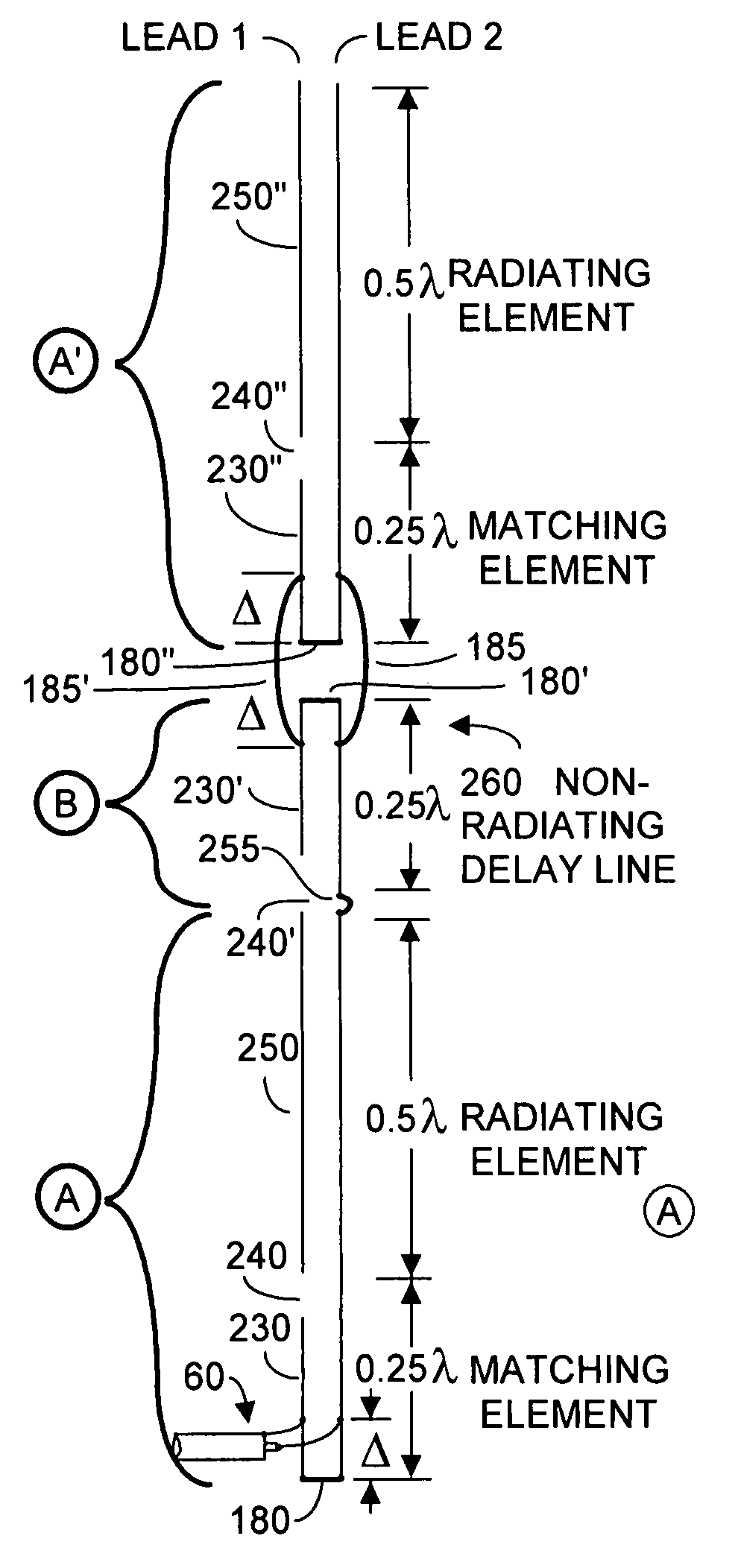
[0037]FIG. 6A depicts an exemplary antenna 270, according to embodiments of the present invention. Antenna 270 comprises a first J-pole section denoted {circle around (A)}, a first quarter-wavelength non-radiating delay line section denoted {circle around (B)}, and a second J-pole section denoted {circle around (C)}. First J-pole section {circle around (A)} is similar to what has been described with respect to FIG. 5, and includes spaced-apart parallel first and second leads that form a quarter-wave matching element 230 whose first, lower, end has the two leads connected together by a short 180 to form an RF low impedance end, preferably 0Ω. The lead 2 side of element 230 extends about a quarter-wavelength at the nominal frequency of interest and has a high impedance second end. Lead 1 has a notch or gap 240 cut into the wire for a length of perhaps 0.25″. In FIG. 6A, below the level of notch 240 is the quarter-wavelength matching element, and above the notch is a half-wavelength ra...


PUM


Abstract

An omni-directional antenna operable absent ground radials and providing at least 3 dB gain at a chosen wavelength relative to a dipole includes first and second like-oriented J-pole antennas and, coupled intermediate said J-pole antennas, a quarter-wavelength non-radiating delay line. Each J-pole antenna includes a half-wave radiating element, and a quarter-wavelength non-radiating section. The quarter-wavelength non-radiating delay line together with the quarter-wavelength non-radiation section of the second J-pole provide a half-wave non-radiating delay line. The result is that RF energy radiated by the first and second half-wave radiating elements are in proper phase, whereby gain is achieved. RF energy is coupled to the first J-pole antenna a distance Δ above the zero impedance end of that antenna.

Description

FIELD OF THE INVENTION[0001]The invention relates generally to antennas that radiate and receive radio frequencies (RF), and preferably for such antennas designed for use in the very high frequency (VHF) range or ultra high frequency range (UHF) that do not require radials or connection to absolute ground. Preferably such antennas should be mechanically robust over extremes of temperature and wind conditions, and should be relatively inexpensive to mass produce and transport, and should be maintenance free. Further, such antennas should exhibit gain.BACKGROUND OF THE INVENTION[0002]Radio frequency (RF antennas are used to receive and / or radiate RF signals. An effective antenna for use in transmission will exhibit an acceptably low standing wave ratio (SWR) at the frequencies of interest, and will present a reasonably good impedance match to the output of the transmitter, typically 50Ω to 75Ω. While some antenna designs such as beams exhibit directionality, i.e., more antenna gain in...

Claims


Application Information

Patent Timeline
Patent Type & Authority Patents(United States)
IPC IPC(8): H01Q9/04H01Q9/30H01Q9/42
CPCH01Q9/42H01Q9/30
Inventor FONG, EDISON
Owner FONG EDISON
Why Eureka
Try Eureka