
Temperature activated optical films

a technology of temperature-activated optical films and dielectric optical structures, which is applied in the direction of instruments, polarising elements, lighting and heating apparatuses, etc., can solve the problems of not being able to adjust the solar energy control at the room temperature range, the system is not useful for the present application, and the technology is less attractive for window applications, etc., to achieve low transition temperature range, low infrared transmittance, and high visible light transmittance

Inactive Publication Date: 2010-05-13
PACIFIC COAST BUILDING PRODS
View PDF92 Cites 51 Cited by
  • Summary
  • Abstract
  • Description
  • Claims
  • Application Information

AI Technical Summary

Benefits of technology

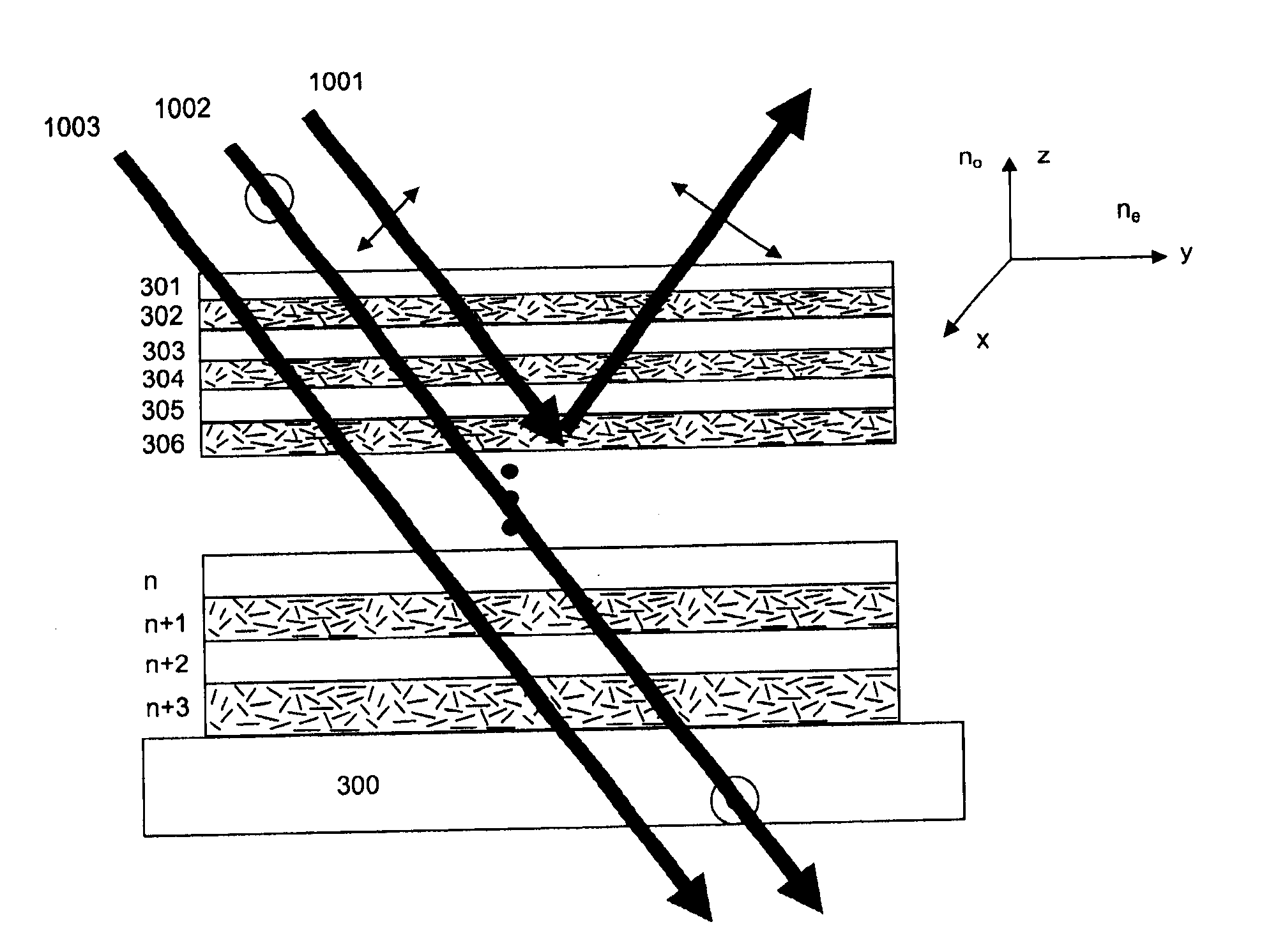
[0020]Another objective of the present invention is to provide a flexible optical film structure where the film transmits the visible light at all temperatures but reflects the near infrared or heat generating spectrum of solar electromagnetic radiation above a desired temperature setting but allows the transmission of such solar heat at lower temperatures.
[0022]Another principle objective of the present invention is to provide such an optical film that is plastic film based and that it is readily mass producible and can be readily retrofit into existing windows as well.

Problems solved by technology

This system is not useful for present application because its temperature dependence changes slowly over a wide range of temperature.
A significant difficulty in implementing such a device, aside from any performance issues, is that there must be a significant reservoir to hold such solvents.
In addition, vanadium oxides in temperatures below or above the transition temperature absorb a significant portion of visible light, which makes the technology less attractive for window applications.
However, the optical properties including its reflectance will not change with the temperature, and the resulting optical structure will reject solar energy on a warmer summer day, which is desirable, as well as on a cold winter day if so designed, which is not desirable.
However, the transition temperature of ferroelectric materials occur at about 120° C., the induced index of refraction change is about 0.03, and as both layers are optically isotropic in the reflection mode at high temperature, the device will only reflect a nearly normal incident single wavelength light at very high temperatures, and it will require a large number of layers, greater than 5000 to achieve significant reflection across a broadband of near infrared radiations, therefore that will not be applicable for adjusting solar energy control at room temperature range.

Method used


Image

  • Temperature activated optical films
  • Temperature activated optical films
  • Temperature activated optical films

Examples


Embodiment Construction

[0033]As used herein, “a” or “an” means one or more.

[0034]As used herein, “Polarization” means the orientation of the electric field oscillations in the plane perpendicular to the electromagnetic wave's direction of travel.

[0035]As used herein, “μm” means micro meter, 1 / 1000000 of a meter in length.

[0036]As used herein, “nm” means nano meter, 1 / 1000000000 of a meter in length.

[0037]As used herein, “birefringent” and “birefringence” means an optical material that shows different effective index of refraction along different directions.

[0038]As used herein, “Optical axis” and “optical axes” means the principal direction or directions of the index ellipsoid of a birefringent material. For biaxial birefringent materials, there are three mutually perpendicular optical axis. For uniaxial materials, typically only one axis, the direction along the extraordinary index of refraction is used.

[0039]As used herein, “refractive index along an optical axis” means a numerical number that measures ...


PUM

PropertyMeasurementUnit
wavelengthsaaaaaaaaaa
transition temperatureaaaaaaaaaa

Abstract

The present invention discloses a multilayer dielectric optical structure wherein one of the optical materials in the multilayer structure shows an optically isotropic state above and a birefringent state below a characteristic temperature Tc near the room temperature. The optical structure reflects a predetermined wavelength range of electromagnetic radiation above the Tc but allow the same to transmit through below the Tc. The predetermined wavelength can be the near infrared radiation from 700 nm to 2500 nm, and the optical structure rejects solar heat in warm summer days but admits the same to interior on a colder winter day.

Description

CROSS-REFERENCE[0001]This application is a continuation of U.S. Non-Provisional application Ser. No. 12 / 152,969, filed May 19, 2008, which claims the benefit of U.S. Provisional Application No. 60 / 930,894, filed May 18, 2007, the contents of both of which are incorporated herein by reference in their entirety.BACKGROUND OF THE INVENTION[0002]The present invention generally relates to a multilayer dielectric optical structure that selectively reflects a predetermined wavelength of electromagnetic radiation. More particularly, this invention relates to the optical structure whose change of optical property is activated by temperature.[0003]Glass windows are widely used in residential and commercial buildings for the purpose of natural light collection as well as for aesthetic reasons. However, glass windows, as they are generally a thin and transparent barrier separating the interior for example an office space to the outside environment, can readily exchange heat with the outside env...

Claims


Application Information

Patent Timeline
Patent Type & Authority Applications(United States)
IPC IPC(8): G02F1/19G02B5/30
CPCG02B5/285G02B5/287G02F1/21G02F1/0147G02B5/3016
Inventor XUE, JIUZHI
Owner PACIFIC COAST BUILDING PRODS
Learn More