Fracture monitoring

a technology of fracturing and monitoring, applied in the direction of survey, instruments, borehole/well accessories, etc., can solve the problems of difficult installation downhole, limited dynamic range of geophones, fracturing of rocks, etc., and achieve the effect of acoustically excitation of the well bor

Active Publication Date: 2015-02-10
OPTASENSE HLDG LTD
View PDF18 Cites 52 Cited by
  • Summary
  • Abstract
  • Description
  • Claims
  • Application Information

AI Technical Summary

Benefits of technology

[0060]As well as detecting proppant washout during the fracturing process the method may comprise the step of identifying any potential points of failure of the casing and/or surrounding cement prior to the hydraulic fracturing step. As mentioned above the DAS sensor may be operated during firing of the perforation charges. Firing of the perforation charges will create a relatively intense series of acoustic pulses that will effectively acoustically excite the well bore. As mentioned above the optic fibre may be embedded in the cement surrounding the casing. The vibrations transmitted to the optic fibre will therefore partly depend on the nature of the casing and surrounding cement. In place where the cement and casing are solid the sensing p

Problems solved by technology

A problem with such an approach is that geophones tend to be relatively large and so installation downhole is difficult.
In addition geophones tend to have limited dynamic range.
This fluid is therefore forced into the perforations and, when sufficient pressure is reached, causes fracturing of the rock.
However control and monitoring of the fracture process is very difficult.
One possible problem, known as proppant wash-out, occurs when the cement surrounding the casing has failed and the fluid is simply flowing into a void.
Another problem relates to a situation that can develop where most of the fluid and proppant flows to the rock formation via one or more perforations, preventing effective fracturing via other perforation sites.
During the hydraulic fracturing process however it is possible that the rock at one or more perforation sites may fracture more readily than at the remaining perforations.
Increasing the flow rate of fluid and proppant may simply lead to increased fracturing at the first peroration site which may simply enlarge the fracture and not have a significant impact on how much oil or gas is received via that fracture.
However reduced fracturing at the other s

Method used


Image

  • Fracture monitoring
  • Fracture monitoring
  • Fracture monitoring

Examples


Embodiment Construction

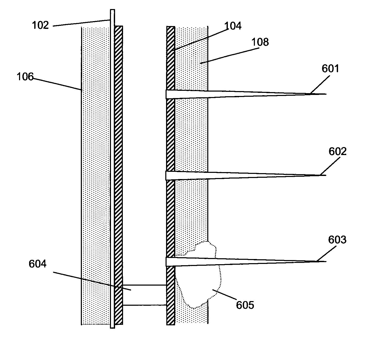
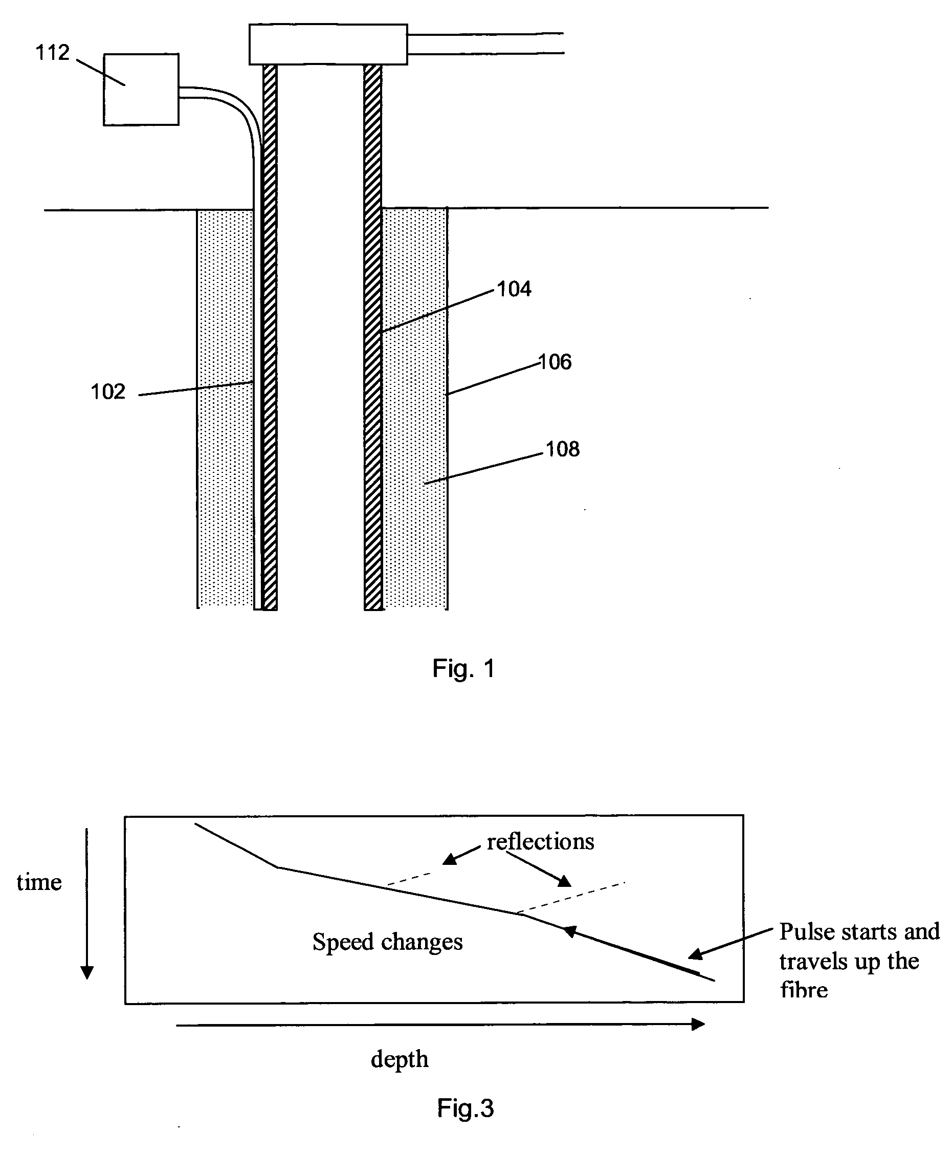
[0076]A fibre optic cable 102 is included along the path of a well, which in the present example is a gas well, and may be on or offshore. The well is formed at least in part by a metallic production casing 104 inserted into a bore hole 106, with the space between the outer wall of the casing and the hole being back filled with cement 108 in the present example. The production casing may be formed of multiple sections joined together, and in certain instances the sections will have different diameters. In this way the casing diameter is able to narrow gradually towards the bottom of the well. As can be seen in FIG. 1, in this example the fibre passes through the cement back fill, and is in fact clamped to the exterior of the metallic casing. It has been found that an optical fibre which is constrained, for instance in this instance by passing through the cement back fill, exhibits a different acoustic response to certain events to a fibre which is unconstrained. An optical fibre whi...


PUM


Abstract

This application relates to methods and apparatus for monitoring hydraulic fracturing during oil/gas well formation. A fiber optic cable (102) deployed down a well bore (106), which may be the well bore in which fracturing is performed, is interrogated to provide a distributed acoustic sensor. Data is sampled from at least one longitudinal sensing portion of the fiber and processed to provide at least fracturing characteristic. The fracturing characteristic may comprise the characteristics of high frequency transients indicative of fracturing events (606). The intensity, frequency, duration and signal evolution of the transients may be monitored to provide the fracturing characteristic. Additionally or alternatively the fracturing characteristic may comprise the longer term acoustic noise generated by fracture fluid flow to the fracture sites. The intensity and frequency of the noise may be analyzed to determine the fracturing characteristic. The method allows real-time control of the fracturing process.

Description

FIELD OF THE INVENTION[0001]The present invention relates to monitoring of fracturing during the formation of production wells such as oil and gas wells. Monitoring of the steps used in formation of such wells and monitoring of such wells in use is often referred to as downhole monitoring. In particular, the present invention relates to downhole monitoring using distributed acoustic sensing (DAS).BACKGROUND OF THE INVENTION[0002]Fibre optic sensors are becoming a well-established technology for a range of applications, for example geophysical applications. Fibre optic sensors can take a variety of forms, and a commonly adopted form is to arrange a coil of fibre around a mandrel. Point sensors such as geophones or hydrophones can be made in this way, to detect acoustic and seismic data at a point, and large arrays of such point sensors can be multiplexed together using fibre optic connecting cables, to form an all fibre optic system. Passive multiplexing can be achieved entirely opti...

Claims


Application Information

Patent Timeline
IPC IPC(8): E21B43/26E21B47/00E21B43/1185E21B47/10E21B47/12G01H9/00G01V1/50
CPCE21B47/101E21B43/11857E21B43/26E21B47/123G01V1/50G01H9/004G01V2210/646G01V2210/1429E21B43/267E21B47/107E21B47/135G01V8/02E21B47/14G01N29/036G01V8/16E21B47/09E21B47/16
Inventor HILL, DAVID JOHNMCEWEN-KING, MAGNUSTINDELL, PATRICK
Owner OPTASENSE HLDG LTD
Why Eureka
Try Eureka