Rotor blade arrangement and gas turbine

a technology of rotor blades and gas turbines, applied in the field of turbines, can solve the problems of increased leakage, different increased load on stator blades, etc., and achieves the effect of high decoupling of platform deformation and blade aerofoil deformation

Inactive Publication Date: 2015-02-10
ANSALDO ENERGIA IP UK LTD
View PDF33 Cites 8 Cited by
  • Summary
  • Abstract
  • Description
  • Claims
  • Application Information

AI Technical Summary

Benefits of technology

[0015]One of numerous aspects of the present invention relates to a rotor blade arrangement, especially for a gas turbine, which can avoid the disadvantages of known rotor blades and, with simultaneously simpler producibility, includes high decoupling of the platform deformations and blade aerofoil deformations.
[0016]Another aspect relates to a rotor blade arrangement which comprises a blade aerofoil element and a platform element, wherein the platform elements of a blade row form a continuous inner shroud, and the blade aerofoil element and platform element are formed as separate elements and can be fastened in each case separately on the blade carrier. As a result, a decoupling of the elements is achieved which has a prolonging effect upon the service life.
[0017]When adhering to principles of the present invention, a rotor blade arrangement is created which, on account of the decoupling of the platform deformations and blade aerofoil deformations, can have the following advantages:

Problems solved by technology

Consequently, the loading of stator blades and rotor blades is inevitably increased.
Stator blades, however, are exposed to different loads than rotor blades because the centrifugal forces which are created as a result of the rotation of the machine are not applied in the case of stator blades.
However, the complex construction of the blade and the multiplicity of additional sealing joints which are associated with it, which in this case can also lead to increased leakage, is disadvantageous.
In this case it is especially also disadvantageous that the forces which act on the blade aerofoil are not introduced directly into the blade carrier but via the blade root which is provided with the platform.
The decoupling between the segments, however, is low or even non-existent and the method is very costly.

Method used


Image

  • Rotor blade arrangement and gas turbine
  • Rotor blade arrangement and gas turbine
  • Rotor blade arrangement and gas turbine

Examples


Embodiment Construction

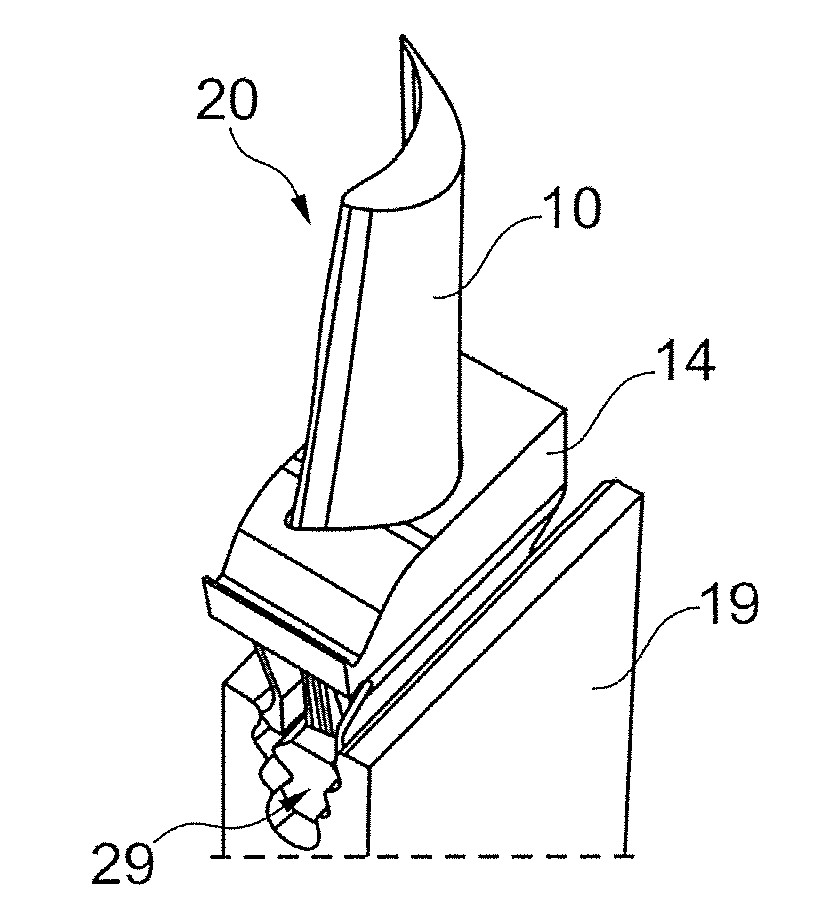
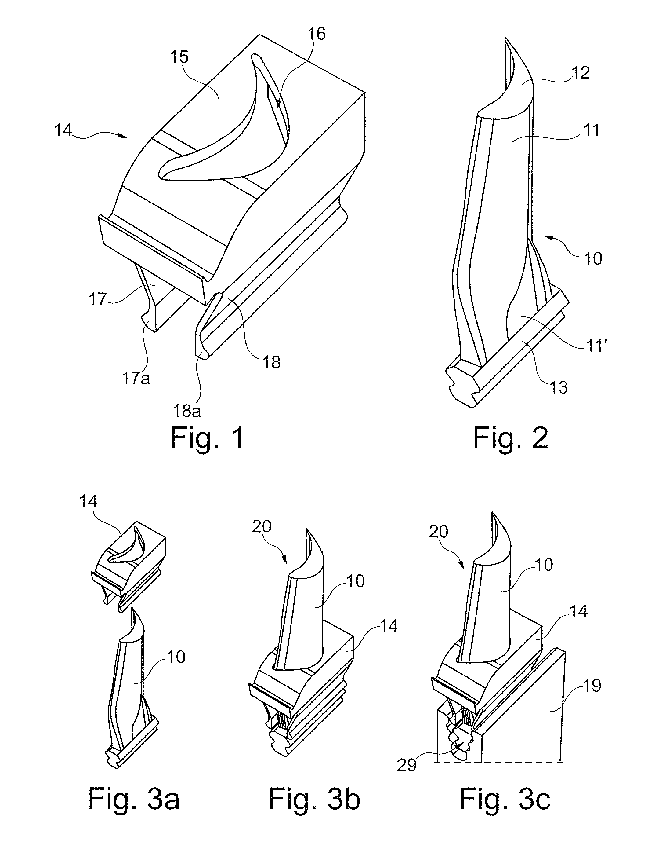
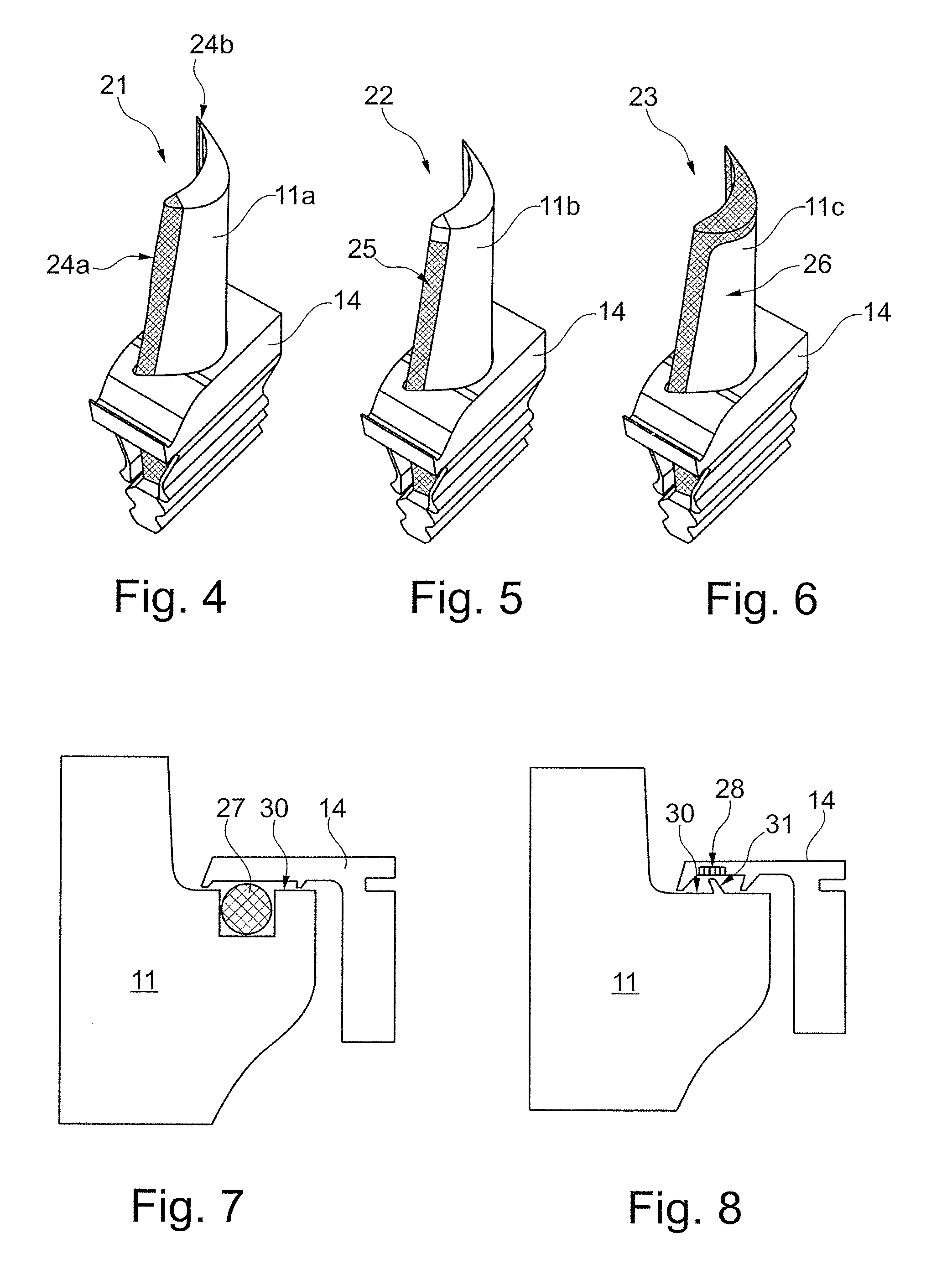
[0053]In general terms, one goal, in the case of a rotor blade of a gas turbine, is to avoid or to reduce the constrained stress as a consequence of varied deformation, which is induced as a result of varied temperature load and geometric notch effects. This can be achieved by separating the blade into a platform element and a blade aerofoil element as individual elements or individual components. The sealing gap which ensues as a result of the form-fitting connection between the individual elements in this case should be sealed so that force transmission no longer takes place between the individual elements in the machine during operation. The platform element in one exemplary embodiment in this case is pushed over the blade aerofoil element. In another exemplary embodiment, the platform element is arranged in each case between two adjacent blade aerofoil elements. The blade aerofoil element and the platform element are fastened separately on the rotor (blade carrier) so that the f...


PUM


Abstract

A rotor blade arrangement (20), especially for a gas turbine, which can be fastened on a blade carrier (19) and includes in each case a blade aerofoil element (10) and a platform element (14), wherein the platform elements (14) of a blade row form a continuous inner shroud. With such a blade arrangement, a mechanical decoupling, which extends the service life, is achieved by the blade aerofoil element (10) and the platform element (14) being formed as separate elements and by being able to be fastened in each case separately on the blade carrier (19).

Description

[0001]This application claims priority under 35 U.S.C. §119 to Swiss application no. 01809 / 08, filed 20 Nov. 2008, the entirety of which is incorporated by reference herein.BACKGROUND[0002]1. Field of Endeavor[0003]The present invention relates to the field of turbines, and to a rotor blade arrangement.[0004]2. Brief Description of the Related Art[0005]Blades for gas turbines, which are used in the compressor section or turbine section as stator blades or rotor blades, are customarily produced as one component by forging or precision casting. This especially also applies to blades which have a platform and / or a shroud segment.[0006]The increase of efficiency and performance of modern gas turbine plants, which is necessary for environmental protection reasons, requires raising the hot gas temperature and reduction of the cooling air consumption (active cooling and leakage). Consequently, the loading of stator blades and rotor blades is inevitably increased. This can be counteracted, ...

Claims


Application Information

Patent Timeline
Patent Type & Authority Patents(United States)
IPC IPC(8): F01D5/26F01D5/30F01D5/14
CPCF01D5/147F01D5/3007F01D5/3092F05D2260/36F05D2240/30F01D11/008F01D5/303F01D9/04
Inventor BRANDL, HERBERTBOSSMANN, HANS-PETERINDLEKOFER, PHILIPP
Owner ANSALDO ENERGIA IP UK LTD
Why Eureka
Try Eureka