Implementing graphene interconnect for high conductivity applications

a graphene interconnect and high conductivity technology, applied in the field of methods, can solve the problems of limited current carrying capacity, significant design challenges for upcoming server systems, and localized warps, and achieve the effect of high conductivity

Inactive Publication Date: 2015-02-10
INT BUSINESS MASCH CORP
View PDF26 Cites 20 Cited by
  • Summary
  • Abstract
  • Description
  • Claims
  • Application Information

AI Technical Summary

Benefits of technology

[0005]Principal aspects of the present invention are to provide a method, and structures for implementing enhanced interconnects for high conductivity applications. Other important aspects of the present invention are to provide such method and structures substantially without negative effects and to overcome many of the disadvantages of prior art arrangements.
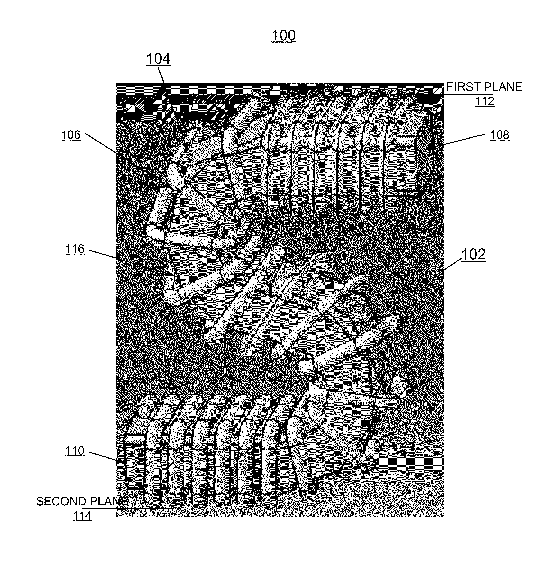
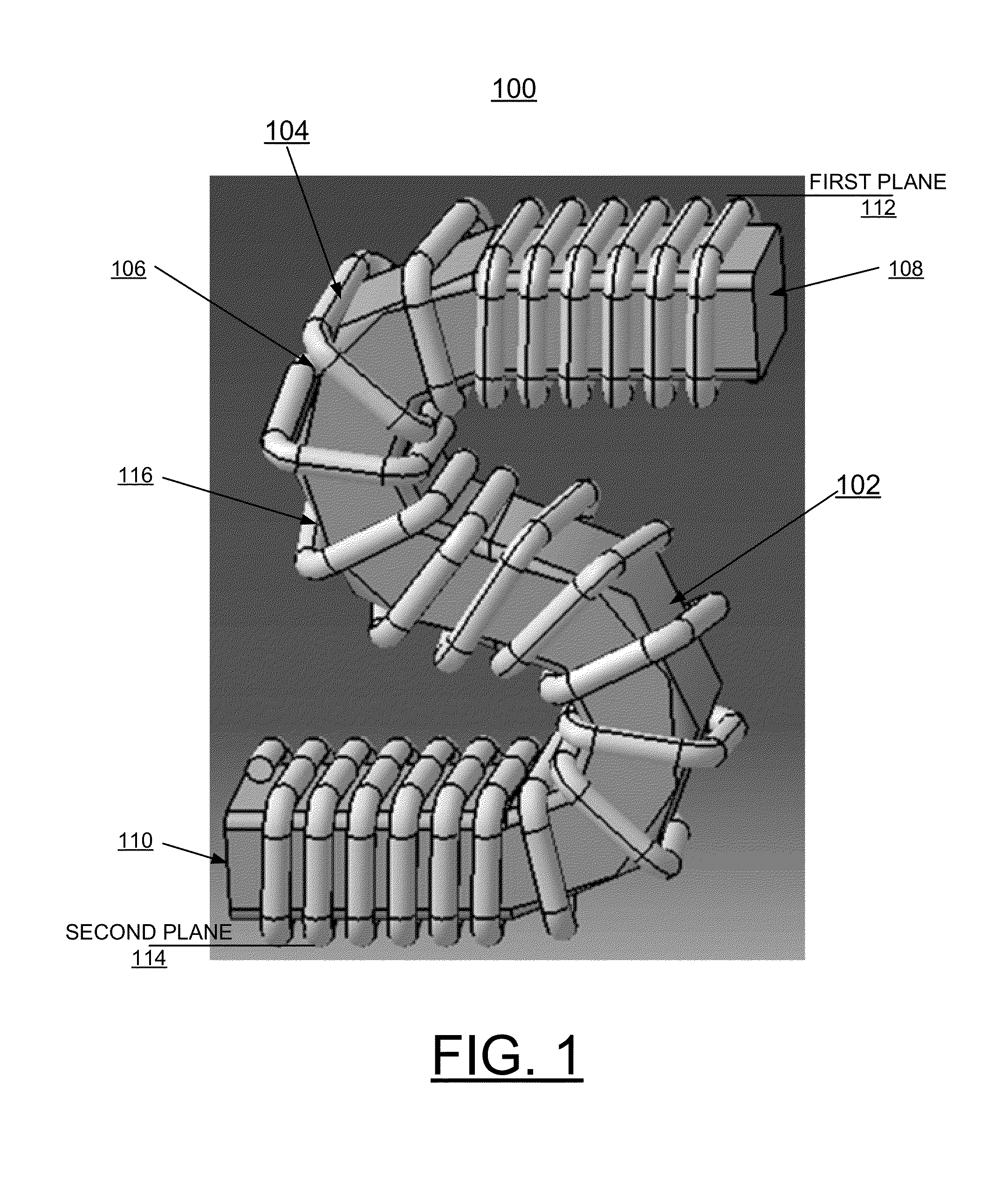
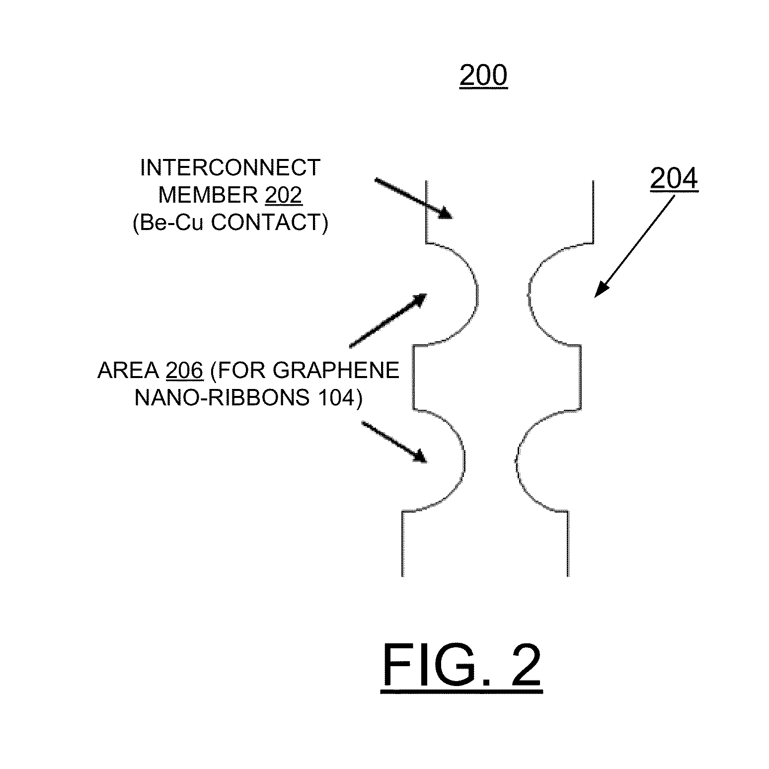
[0006]In brief, a method, and structures for implementing enhanced interconnects for high conductivity applications. An interconnect structure includes an electrically conductive interconnect member having a predefined shape with spaced apart end portions extending between a first plane and a second plane. A winded graphene ribbon is carried around the interconnect member, providing increased electrical current carrying capability and increased thermal conductivity.
[0011]In accordance with features of the invention, providing the winded graphene ribbon enables substantially increased electrical current carrying capability, for example increased by 10 times, without substantially increasing Joule heating.

Problems solved by technology

As power requirements continue to rise for high performance computer CPU, I / O, and memory sub-systems, the current carrying capability limitations of connector contacts or interconnects can create significant design challenges for upcoming server systems, and for other complex systems.
One of the main drawbacks of connector contacts or interconnects is limited current carrying capability.
This current carrying limitation typically requires distribution of total current for a package over a larger area.
Currently the distribution of total current for a package over a larger area can result in a localized warp and typically requires tighter process parameter controls.

Method used


Image

  • Implementing graphene interconnect for high conductivity applications
  • Implementing graphene interconnect for high conductivity applications
  • Implementing graphene interconnect for high conductivity applications

Examples


Embodiment Construction

[0016]In the following detailed description of embodiments of the invention, reference is made to the accompanying drawings, which illustrate example embodiments by which the invention may be practiced. It is to be understood that other embodiments may be utilized and structural changes may be made without departing from the scope of the invention.

[0017]The terminology used herein is for the purpose of describing particular embodiments only and is not intended to be limiting of the invention. As used herein, the singular forms “a”, “an” and “the” are intended to include the plural forms as well, unless the context clearly indicates otherwise. It will be further understood that the terms “comprises” and / or “comprising,” when used in this specification, specify the presence of stated features, integers, steps, operations, elements, and / or components, but do not preclude the presence or addition of one or more other features, integers, steps, operations, elements, components, and / or gr...


PUM

PropertyMeasurementUnit
conductivityaaaaaaaaaa
electrically conductiveaaaaaaaaaa
electrical current carrying capabilityaaaaaaaaaa

Abstract

A method, and structures for implementing enhanced interconnects for high conductivity applications. An interconnect structure includes an electrically conductive interconnect member having a predefined shape with spaced apart end portions extending between a first plane and a second plane. A winded graphene ribbon is carried around the electrically conductive interconnect member, providing increased electrical current carrying capability and increased thermal conductivity.

Description

FIELD OF THE INVENTION[0001]The present invention relates generally to the electrical connector interconnect field, and more particularly, to a method, and structures for implementing graphene interconnects for high conductivity applications.DESCRIPTION OF THE RELATED ART[0002]As power requirements continue to rise for high performance computer CPU, I / O, and memory sub-systems, the current carrying capability limitations of connector contacts or interconnects can create significant design challenges for upcoming server systems, and for other complex systems.[0003]One of the main drawbacks of connector contacts or interconnects is limited current carrying capability. This current carrying limitation typically requires distribution of total current for a package over a larger area. Currently the distribution of total current for a package over a larger area can result in a localized warp and typically requires tighter process parameter controls.[0004]A need exists for efficient and ef...

Claims


Application Information

Patent Timeline
Patent Type & Authority Patents(United States)
IPC IPC(8): H05K1/09
CPCH01R12/52H01R12/55Y10T29/49117
Inventor PLUCINSKI, MARK D.SINHA, ARVIND K.THOMPSON, THOMAS S.
Owner INT BUSINESS MASCH CORP
Why Eureka
Try Eureka