
Power conversion apparatus for electronic apparatus

a technology of power conversion apparatus and electronic equipment, applied in the direction of emergency power supply arrangement, process and machine control, instruments, etc., can solve the problem of significant amount of unnecessary power consumption, and achieve the effect of effective management and economization

Active Publication Date: 2015-02-10
COMPAL ELECTRONICS INC
View PDF38 Cites 1 Cited by
  • Summary
  • Abstract
  • Description
  • Claims
  • Application Information

AI Technical Summary

Benefits of technology

[0007]The invention is directed to a power conversion apparatus which is able to determine a state of an electronic apparatus by means of an external signal from the electronic apparatus. According to the state of the electronic apparatus, the power conversion apparatus may be dynamically turned on or turned off, such that the power consumption of the power conversion apparatus may be effectively managed and economized.
[0014]In view of the above, an external signal is transmitted between the power conversion apparatus described in an embodiment of the invention and an electronic apparatus, and the external signal serves to indicate the state of the electronic apparatus. According to the external signal, the power conversion control unit of the power conversion apparatus is able to determine the state of the electronic apparatus; in addition, the power conversion apparatus may be dynamically turned on or turned off to comply with its requirement for power consumption. Thereby, unnecessary power consumption may be prevented, and the use of power may be economized.

Problems solved by technology

Accordingly, the existing power conversion apparatus is unable to adjust the output power according to the state of the electronic apparatus connected to the power conversion apparatus, which leads to the significant amount of unnecessary power consumption.

Method used


Image

  • Power conversion apparatus for electronic apparatus
  • Power conversion apparatus for electronic apparatus
  • Power conversion apparatus for electronic apparatus

Examples


Embodiment Construction

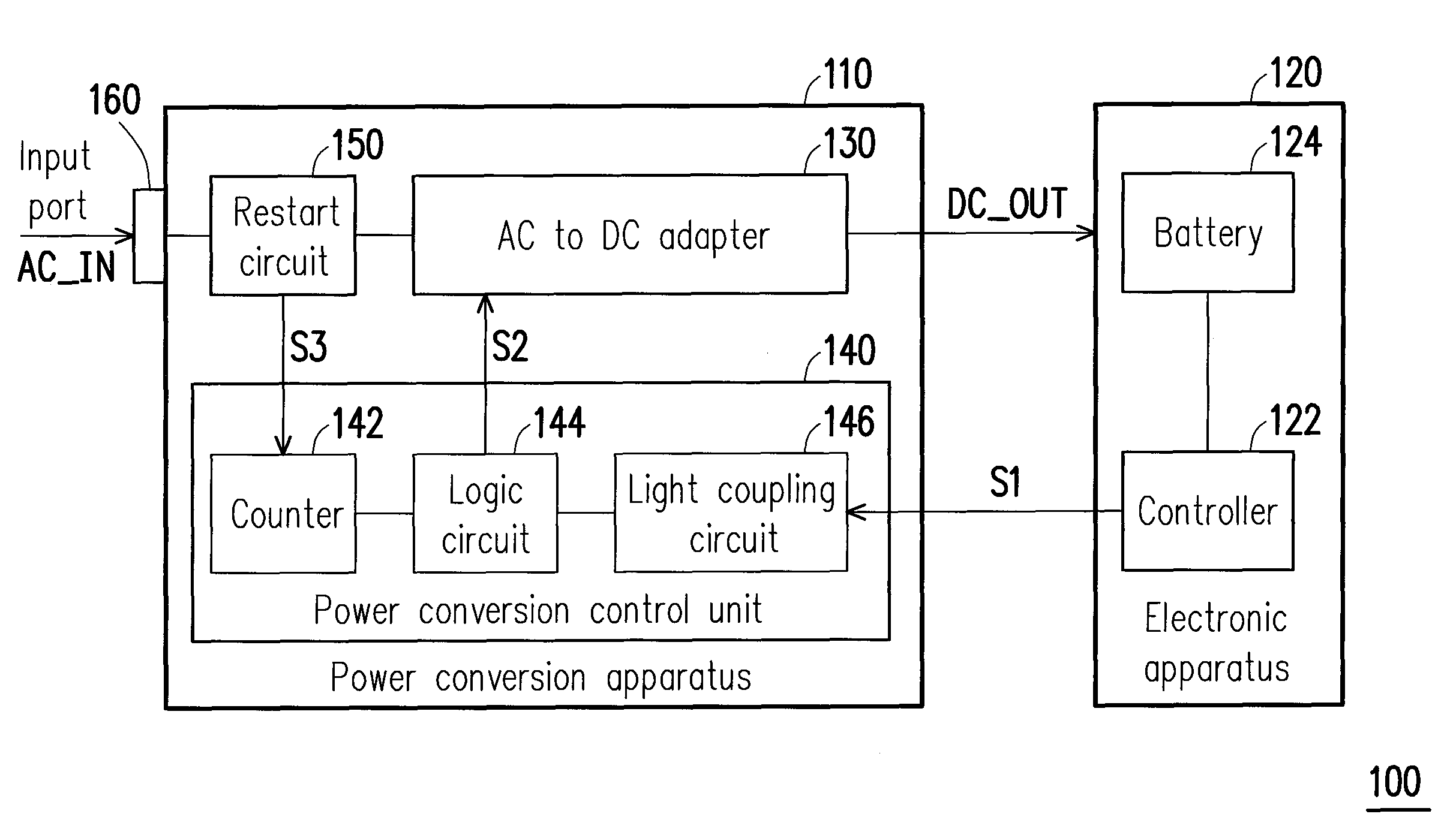
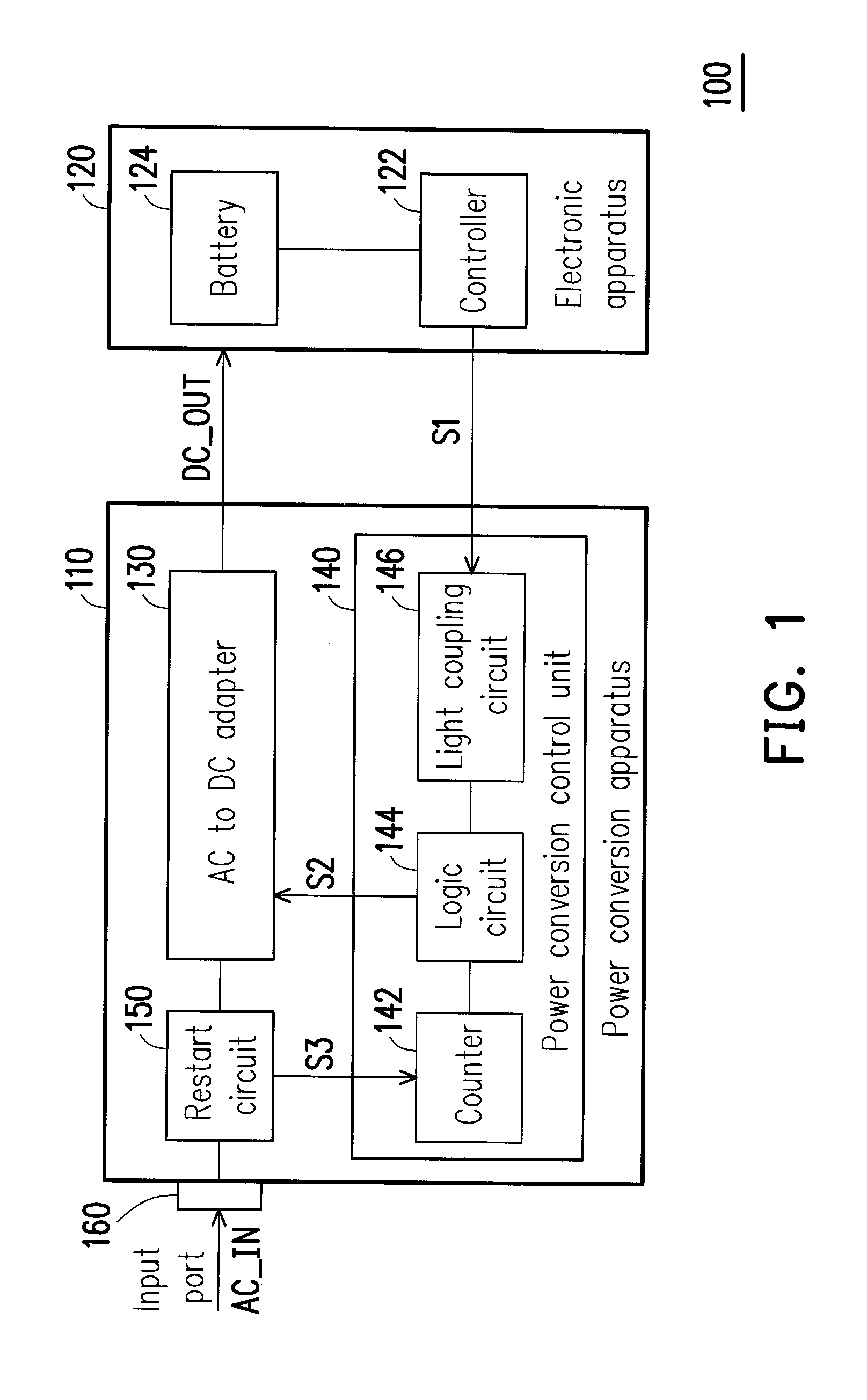
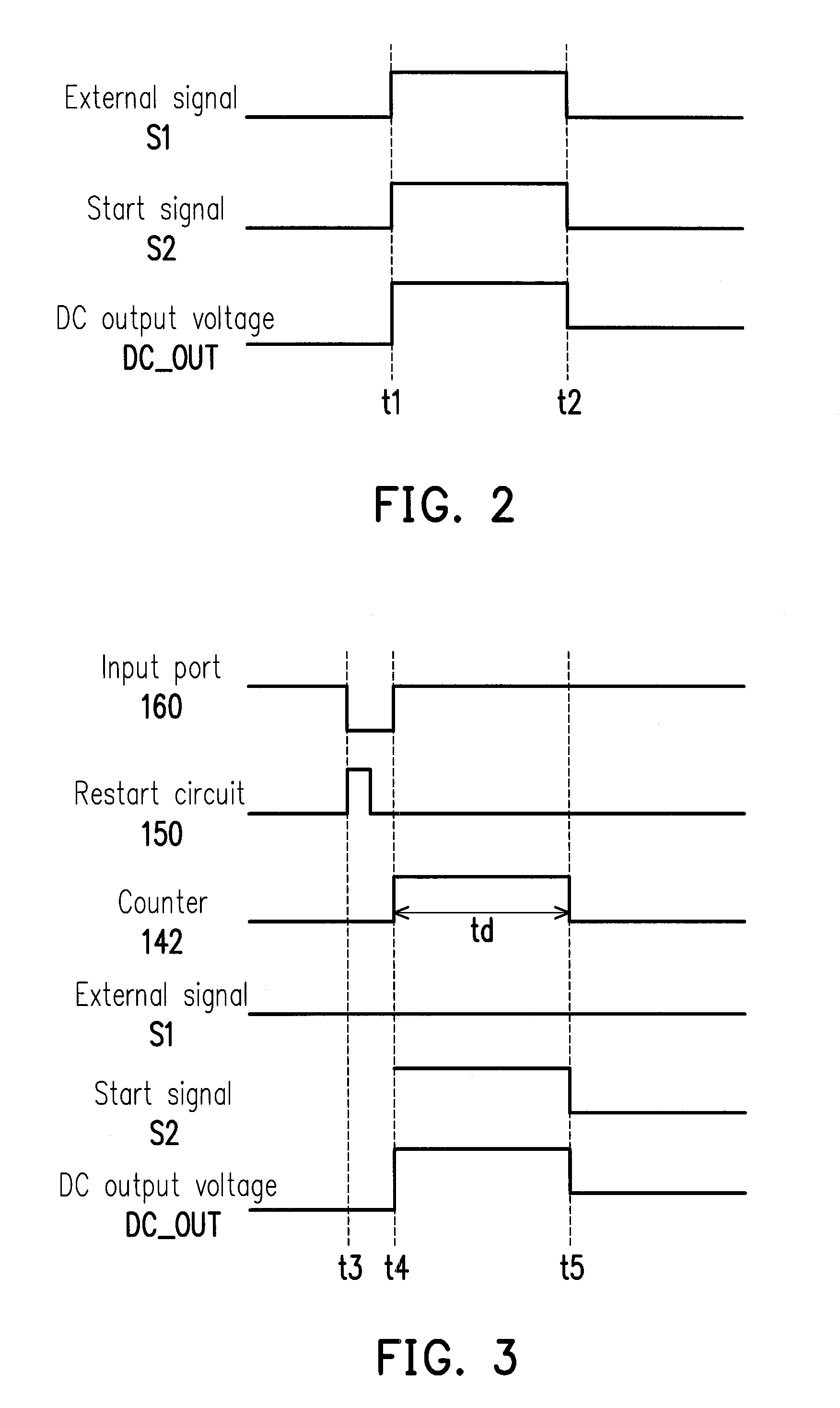
[0022]In order to prevent the power supply system from consuming unnecessary power, an embodiment of the invention provides a power conversion apparatus. An external signal is transmitted between the power conversion apparatus and an electronic apparatus; thereby, the power conversion apparatus is able to learn the power requirement of the electronic apparatus connected to the power conversion apparatus according to the external signal, and the power conversion apparatus may accordingly be dynamically turned on or turned off. As a result, the power conversion apparatus may supply power in a manner complying with the power requirement of the electronic apparatus without consuming unnecessary power.

[0023]It is to be understood that the foregoing and other detailed descriptions, features, and advantages provided in the embodiments of the invention are intended to be described more comprehensively hereinafter with reference to the drawings. In addition, whenever possible, identical or s...


PUM


Abstract

A power conversion apparatus is provided. The power conversion apparatus includes an AC to DC adapter, an input port, a power conversion control unit, and a restart circuit. The AC to DC adapter converts an AC input voltage into a DC output voltage according to an external signal of an electronic apparatus and provides the DC output voltage to the electronic apparatus. The input port receives the AC input voltage through an AC input terminal. If the power conversion apparatus does not output the DC output voltage to the electronic apparatus, the power conversion control unit turns off the power conversion apparatus. If the restart circuit detects that an insertion action occurs on the input port, the restart circuit transmits a trigger signal to turn on the power conversion control unit in an off mode.

Description

CROSS-REFERENCE TO RELATED APPLICATION[0001]This application claims the priority benefits of U.S. provisional application Ser. No. 61 / 740,431, filed on Dec. 20, 2012. The entirety of the above-mentioned patent application is hereby incorporated by reference herein and made a part of this specification.BACKGROUND OF THE INVENTION[0002]1. Field of the Invention[0003]The invention relates to a power control technique and particularly to a power conversion apparatus capable of performing a power saving function.[0004]2. Description of Related Art[0005]At present, due to the requirement for the reduced weight of consumers' electronic apparatuses (e.g., desktop computers, notebooks, mobile phones, digital cameras, tablet PCs, etc.), power may be supplied by batteries within the electronic apparatuses or by external power adapters. That is, the electronic apparatuses require the power conversion apparatuses (e.g., alternating-current (AC) to direct-current (DC) adapters) to supply power or...

Claims


Application Information

Patent Timeline
Patent Type & Authority Patents(United States)
IPC IPC(8): H02M7/217H02M1/36H02M3/335
CPCH02M3/33553H02M1/36H02J9/005Y02B70/10H02M1/0032
Inventor MI, TZU-CHIANGLIN, YI-HSUNLIN, SIOU-YI
Owner COMPAL ELECTRONICS INC
Learn More