
Selectable bandwidth filter

a filter and bandwidth technology, applied in the field of selectable bandwidth filter, can solve the problems of destructive cancellation, phase profiles of the remaining nyquist zones aligned with the m-roots of unity

Inactive Publication Date: 2015-02-17
HARRIS FREDRIC J
View PDF29 Cites 11 Cited by
  • Summary
  • Abstract
  • Description
  • Claims
  • Application Information

AI Technical Summary

Benefits of technology

This patent describes a versatile bandwidth channelizer that can extract time series from a wide range of spectral frequencies. The channelizer uses a combination of filters and a commutator to effectively partition the spectral spans into channels. The resulting aliased sensors have unique phase profiles that can be aligned and summed to create a coherent output signal. The channelizer can be configured with fixed, hardwired multipliers for easy tuning of bandwidth. The technical effects of this patent are improved spectral resolution and greater flexibility for selecting bandwidths over a wide range of fractional bandwidths.

Problems solved by technology

On the other hand, the phase profiles of the remaining Nyquist zones are aligned with the M-roots of unity and are destructively canceled when summed.

Method used


Image

  • Selectable bandwidth filter
  • Selectable bandwidth filter
  • Selectable bandwidth filter

Examples


Embodiment Construction

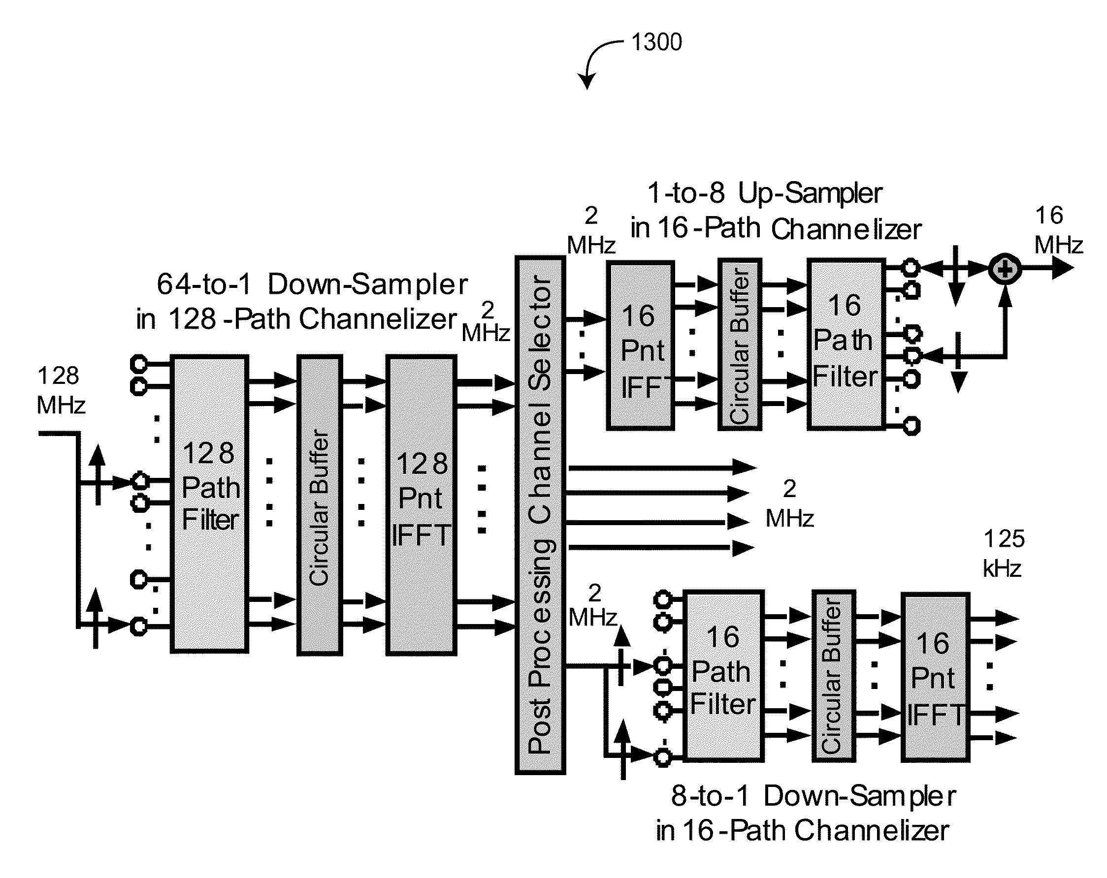
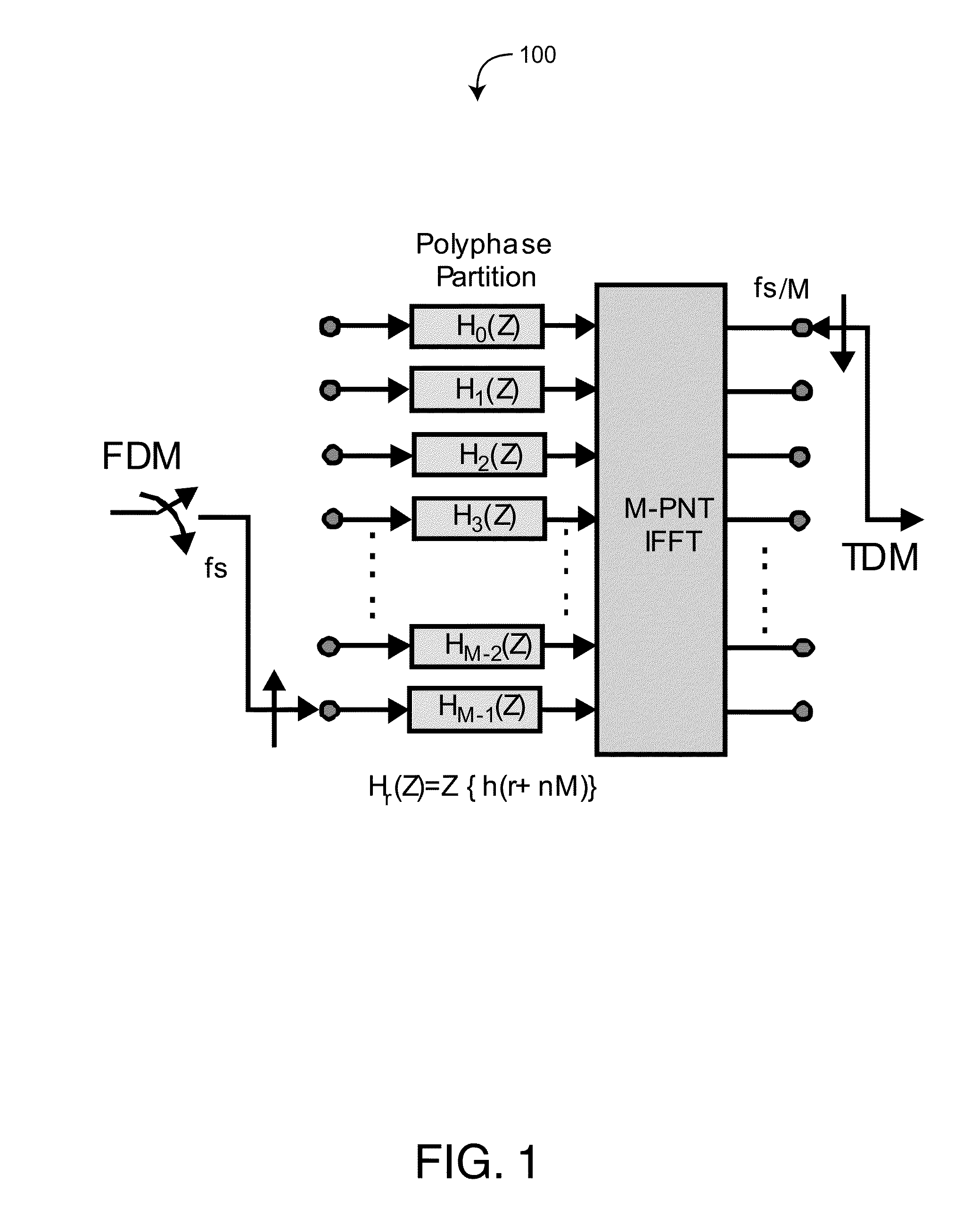
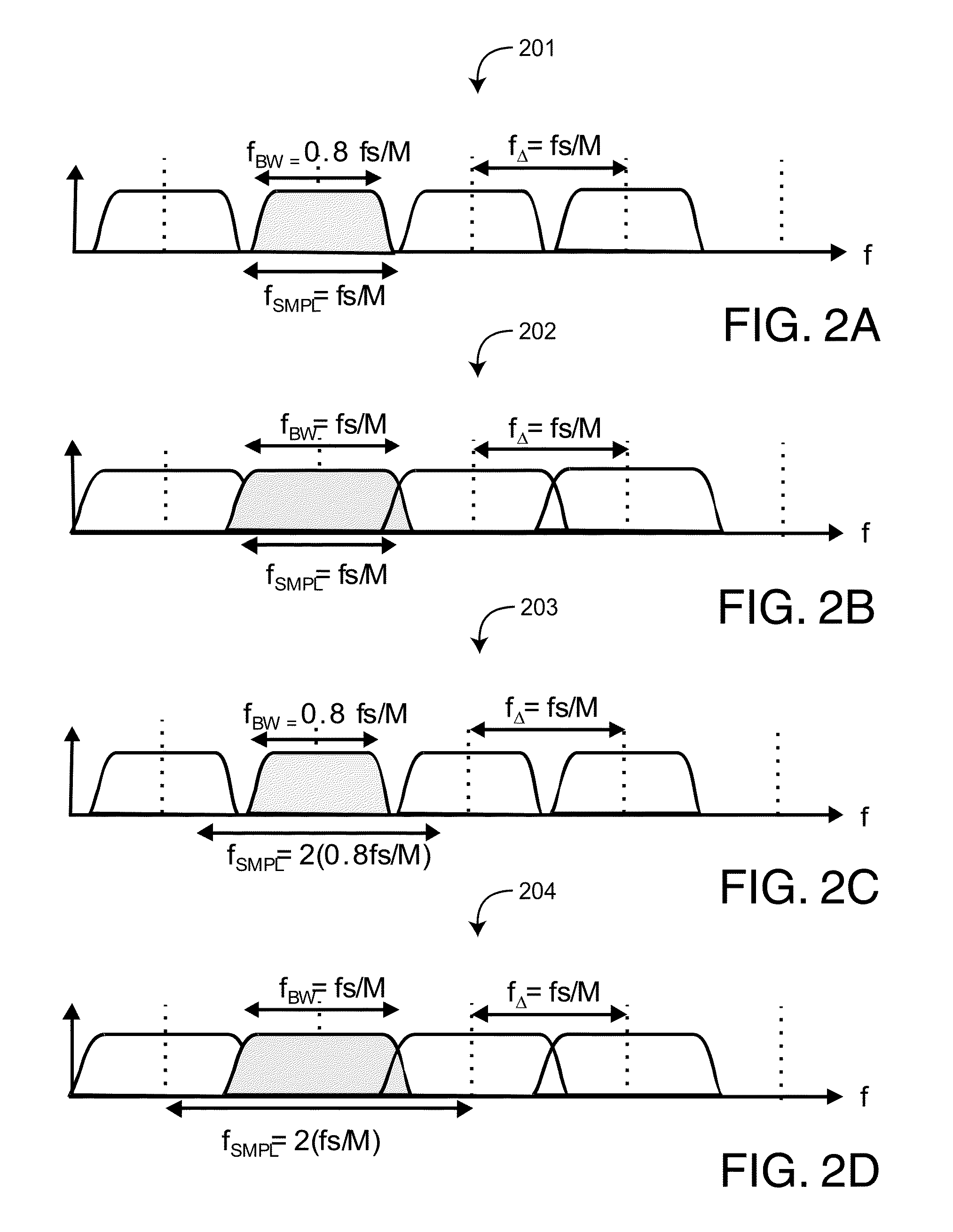
[0026]FIG. 1 illustrates an M-to-1 down sample, M-path polyphase channelizer 100. When the time signals residing in multiple aliased Nyquist zones are to be separated from the M-fold aliased baseband signal, the collection of phase rotators and coherent sums is most efficiently applied to the output of the M-path filter by the inverse fast Fourier transform (IFFT), as shown in this structure of an M-path down-sampler and channelizer. The M-path polyphase channelizer performs three distinct tasks, and these tasks occur in different segments of the channelizer. The first task is the selection of the number of Nyquist zones to be separated by the channelizer. Here the number of zones or channels is defined by M, the size of the IFFT. The M in the M-point transform defines both the width of the successive Nyquist zones and the spacing between channel spectral centers as fS / M, where fS is the input sample rate. The second task is the definition of the channelizer spectral response, which...


PUM


Abstract

A pair of M-path perfect reconstruction filter banks, one for analysis and one for synthesis avoid aliasing of channel filter band-edges by operating at an output sample rate of 2-samples per channel bandwidth. The non-maximally decimated analysis filter performs an M / 2-to-1 down sample operation to obtain the 2-samples per channel output rate. The corresponding synthesis bank accepts signal samples at 2-samples per symbol and up-samples 1-to-M / 2 to obtain the original and desired output sample rate matched to the input sample rate. Changes in composite system bandwidth are achieved by enabling or disabling the connection between the analysis filter bank and the corresponding synthesis filter bank.

Description

PRIORITY CLAIM TO RELATED PROVISIONAL APPLICATIONS[0001]The present application claims priority benefit under 35 U.S.C. §119(e) to U.S. Provisional Patent Application Ser. No. 61 / 353,600 filed Jun. 10, 2010, titled Multichannel Filter Bank with Multiple Channel Bandwidths; and to U.S. Provisional Patent Application Ser. No. 61 / 374,268 filed Aug. 17, 2010, titled Selectable Bandwidth Filter; the above-cited provisional patent applications are both hereby incorporated by reference herein.BACKGROUND OF THE INVENTION[0002]A multichannel digital receiver simultaneously down-converts a set of frequency division multiplexed (FDM) channels residing in a single sampled data signal stream. In a similar way, a multichannel digital transmitter simultaneously up-converts a number of baseband signals to assemble a set of FDM channels in a single sampled data signal stream. The polyphase filter bank has become the architecture of choice to efficiently accomplish these tasks. This architecture uses...

Claims


Application Information

Patent Timeline
IPC IPC(8): H04B1/10
CPCH03H17/0266H03H17/0294H04L27/2631H04L27/26414H04L27/26538H04J1/08
Inventor HARRIS, FREDRIC J.
Owner HARRIS FREDRIC J
Learn More