Distributed power supply system and control method thereof

a power supply system and distribution power technology, applied in the direction of electric variable regulation, process and machine control, instruments, etc., can solve the problem that the fuel cell apparatus 104 consumes electric power, and achieve accurate diagnostic results and electric power values.

Inactive Publication Date: 2015-02-17
PANASONIC INTELLECTUAL PROPERTY MANAGEMENT CO LTD
View PDF6 Cites 17 Cited by
  • Summary
  • Abstract
  • Description
  • Claims
  • Application Information

AI Technical Summary

Benefits of technology

[0037]In accordance with a distributed power supply system and a control method thereof of the present invention, a process for determining whether or not to permit a diagnostic process is executed, and then the diagnostic process is permitted only in a case where detecting accuracy of a current sensor can be guaranteed. Therefore, it is possible to attain a more accurate diagnostic result and a more accurate electric power value.

Problems solved by technology

As a result, the fuel cell apparatus 104 consumes the electric power.

Method used


Image

  • Distributed power supply system and control method thereof
  • Distributed power supply system and control method thereof
  • Distributed power supply system and control method thereof

Examples


embodiment 1

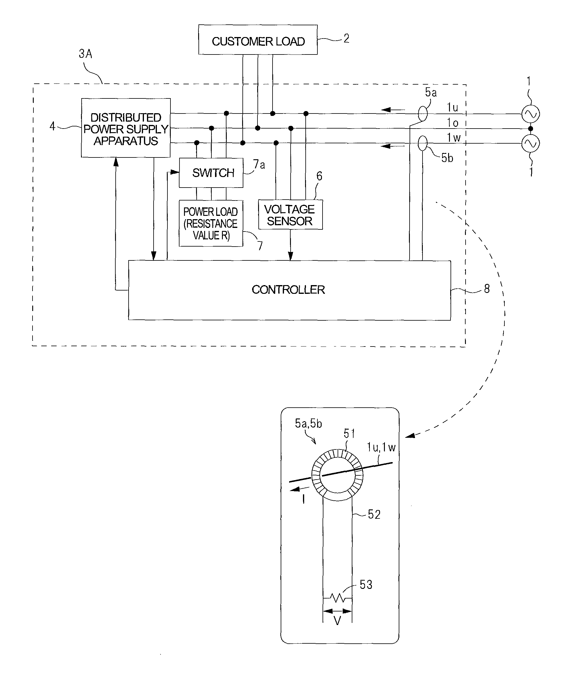
[0050]FIG. 1 is a block diagram showing a configuration of a distributed power supply system according to Embodiment 1 of the present invention. As shown in FIG. 1, a distributed power supply system 3A of the present embodiment is situated between a commercial power utility 1 and a customer load (power demand site) 2. Although in the present embodiment, the commercial power utility 1 is a single-phase three-wire AC power supply composed of U-phase, O-phase and W-phase as the commercial power utility 1, a single-phase two-wire circuit or a two-phase three-wire circuit may be used. The customer load 2 is defined as equipment which consumes electric power, for example, a laundry machine installed at a customer. The customer includes general homes, schools, hospitals, etc.

[0051]The distributed power supply system 3A includes a distributed power supply apparatus 4 which outputs AC power and current sensors 5a, 5b. The distributed power supply apparatus 4 is connected to the commercial po...

embodiment 2

[0079]Next, description will be given of a specific configuration of a distributed power supply system 3B and a specific content of a current sensor diagnostic process executed by the distributed power supply system 3B. FIG. 6 is a block diagram showing a configuration of the distributed power supply system 3B according to Embodiment 2. In the distributed power supply system 3B, the distributed power supply apparatus 4 includes a power generation unit 4a and an inverter 4b. The controller 8 includes a power calculating section 11, a current sensor state determination section 12, a nonvolatile memory 13, a sign inverting section 14 and a power load control section 15.

[0080]The power calculating section 11 calculates a product of a current value from the current sensor 5a(5b) input to the controller 8 and a voltage value from the voltage sensor 6, to derive electric power for each of U-phase and W-phase. The power load control section 15 controls ON / OFF of the switch 7a. The current s...

embodiment 3

[0100]Another specific configuration of a distributed power supply system 3C will be described. FIG. 8 is a block diagram showing a configuration of the distributed power supply system 3C according to Embodiment 3. The distributed power supply system 3C determines whether or not there is an installation problem of the current sensor 5a(5b), disconnection of the winding wire 52, or a failure of current sensor 5a(5b), in the current sensor diagnostic process. As shown in FIG. 8, the distributed power supply system 3C further includes a volatile memory 16, a current sensor abnormality determiner section 17, a switch 18, and a time measuring section 19, which are added to the constituents in the distributed power supply system 3B of Embodiment 2.

[0101]The volatile memory 16 is configured to receive signals from the power calculating section 11 and from the power load control section 15 as inputs. The volatile memory 16 is capable of storing the electric power value calculated by the pow...


PUM


Abstract

A distributed power supply system is configured to execute a process for determining whether or not to permit a diagnostic process in such a manner that it is determined whether or not a difference between a set upper limit value and an actual measurement current value is not less than a load current value, the set upper limit value being a predetermined upper limit value set with respect to a detected current of a current sensor, the measurement current value being detected by the current sensor in a state where the diagnostic process is not executed, and the load current value being a value of a current flowing from a commercial power utility to a power load during execution of the diagnostic process; and if it is determined that the difference is not less than the load current value, the controller permits the diagnostic process.

Description

[0001]This application is a 371 application of PCT / JP2011 / 004361 having an international filing date of Aug. 1, 2011, which claims priority to JP2010-173350 filed Aug. 2, 2010 and JP2010-277585 filed Dec. 14, 2010, the entire contents of which are incorporated herein by reference.TECHNICAL FIELD[0002]The present invention relates to a distributed power supply system which supplies electric power to a power demand site separately from a commercial power utility, and a control method thereof.BACKGROUND ART[0003]Conventionally, as a distributed power supply system, an in-house power generation system disclosed in Patent Literature 1 is proposed. FIG. 10 is a bock diagram showing a configuration of a conventional distributed power supply system disclosed in Patent Literature 1.[0004]As shown in FIG. 10, a distributed power supply system 103 includes a fuel cell apparatus 104 as a distributed power supply apparatus which is interactively connected (interconnected) to commercial power uti...

Claims


Application Information

Patent Timeline
Patent Type & Authority Patents(United States)
IPC IPC(8): G05F3/02G01R35/00H02J3/38
CPCH02J3/38G01R35/00H02J3/381H02J3/387H02J2300/30H02J2300/22H02J2300/28H02J3/46G01R19/145Y02E10/50
Inventor KAKE, NINMIYAUCHI, SHINJIKAKU, HIROAKISATO, KEIICHINAGASATO, HIROSHIOOTANI, AKIHITOKUSHISAKA, TORUKATOU, MOTOMICHITAKAHASHI, MANABU
Owner PANASONIC INTELLECTUAL PROPERTY MANAGEMENT CO LTD
Why Eureka
Try Eureka