
Process of repairing a component, a repair tool for a component, and a component

a technology for repairing tools and components, applied in the field of manufacturing components, can solve problems such as reducing the life capability of components, rotor wheels being out of service for a long time, and accumulation of strain

Active Publication Date: 2015-02-24
GENERAL ELECTRIC CO
View PDF38 Cites 4 Cited by
  • Summary
  • Abstract
  • Description
  • Claims
  • Application Information

AI Technical Summary

Benefits of technology

The patent describes a process for repairing components by removing material from a region in the component. The removal forms a through-cut, a partial-frustoconical geometry, a partial-spherical geometry, a partial-elliptical geometry, a partial-cylindrical geometry, or a combination of these. The repair tool includes a securing mechanism and a cutting portion. The technique allows for the removal of material without compromising the structural integrity of the component and can be used to repair various geometries. The resulting repaired region has improved strength and performance.

Problems solved by technology

The stress is caused by a combination of mechanical cyclic loads and thermal cyclic and static loads which can result in the accumulation of strain over time.
These processes can suffer from drawbacks that they are expensive, are not widely available, involve complex tooling, and result in the rotor wheel being out of service for a long period of time.
However, these uncontrolled processes may introduce undesired high stress concentrations into the dovetail, which may result in reducing the component life capability.
Though the shape and consistency of the edge break helps the part meet the intended service life, this method does not significantly reduce the stress nor remove enough strained material to significantly extend the operating life of the feature.

Method used


Image

  • Process of repairing a component, a repair tool for a component, and a component
  • Process of repairing a component, a repair tool for a component, and a component
  • Process of repairing a component, a repair tool for a component, and a component

Examples


Embodiment Construction

[0023]Provided is a process of repairing a component, a repair tool for a component, and a component. Embodiments of the present disclosure permit extended useful life of components, reduce or eliminate crack propagation, permit increased operational performance of turbines, increase resistance to fatigue, or combinations thereof.

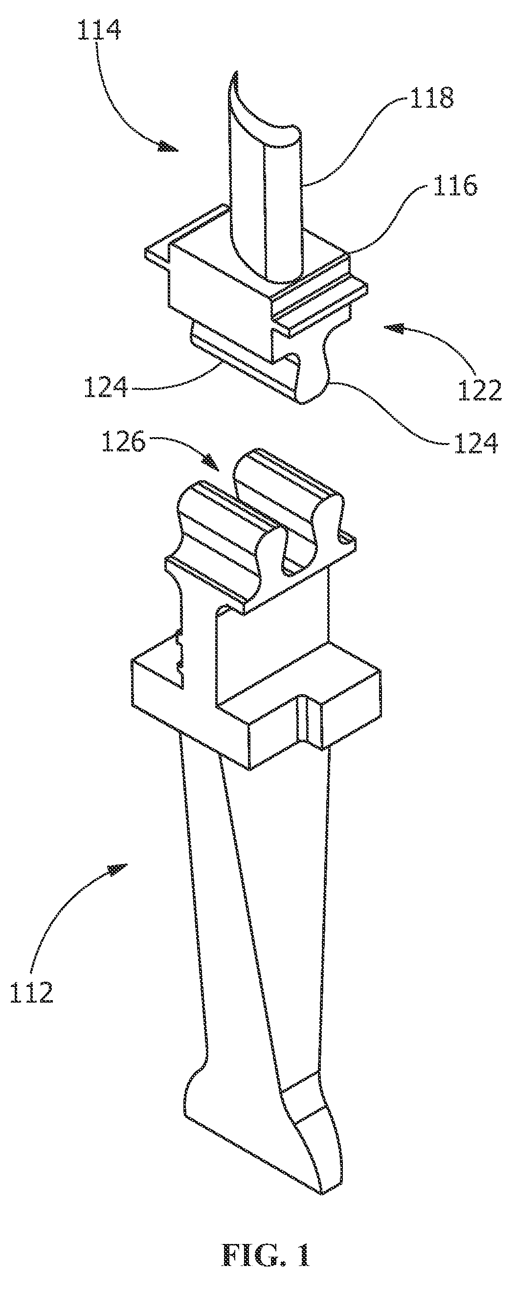
[0024]FIG. 1 is a perspective view of portions of a turbine 110 including a rotor wheel 112 and a blade 114 according to an embodiment. Generally, the turbine 110 includes a plurality of the rotor wheels 112, blades 114, and other turbine components (for example, a compressor, a shaft, vanes, rotor dovetails, and / or other suitable components). Fluid (such as gas) enters the turbine 110 (for example, through an inlet) and is channeled (for example, through the vanes) downstream against the blades 114 and through the remaining stages imparting a force on the blades 114 causing rotor wheels 112 to rotate (for example, around the shaft) or vice versa. The turbi...


PUM

PropertyMeasurementUnit
temperaturesaaaaaaaaaa

Abstract

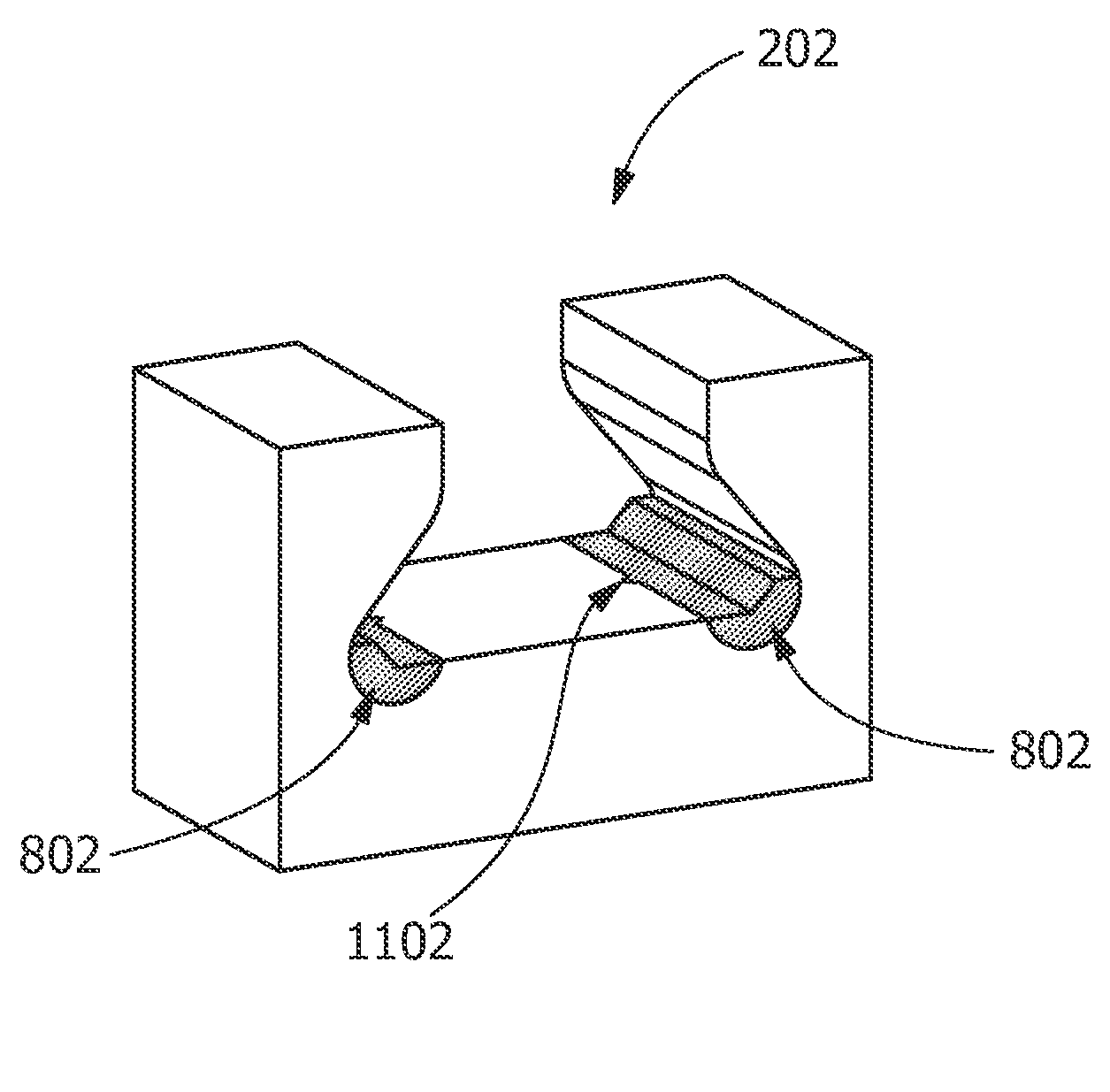
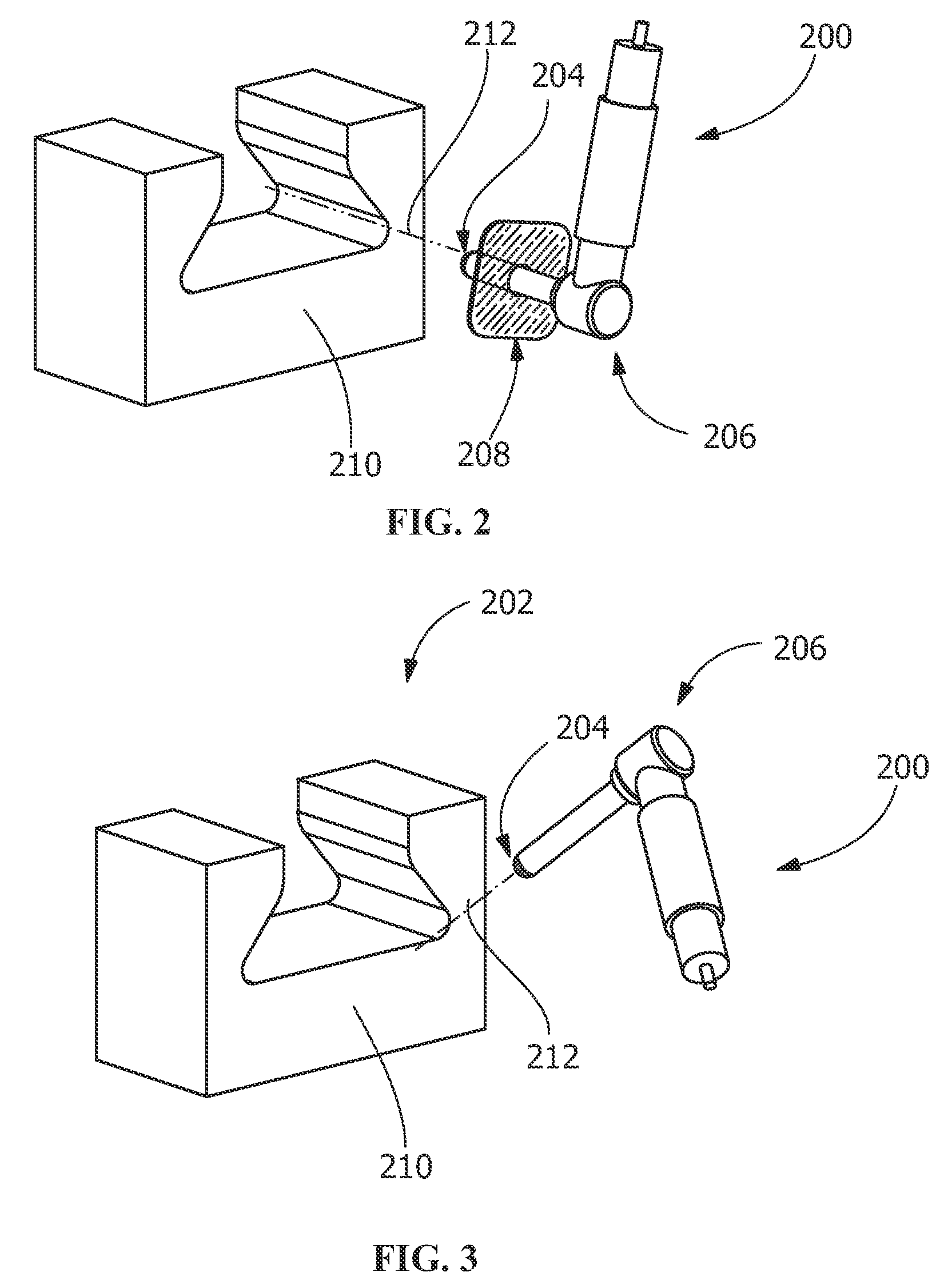
A process of repairing a component, a repair tool for a component, and a component are disclosed. The process includes removing material from a region of the component. The removing forms a through-cut in the component, forms a partial-frustoconical geometry in the component, forms a substantially partial-frustoconical geometry in the component, forms a partial-spherical geometry in the component, forms a substantially partial-spherical geometry in the component, forms a partial-elliptical geometry in the component, forms a substantially partial-elliptical geometry in the component, forms a partial-cylindrical geometry in the component, forms a substantially partial-cylindrical geometry in the component, is in a direction substantially perpendicular to a surface of the component, is in a direction substantially inclined with respect to the surface of the component, or a combination thereof. The repair tool includes a securing mechanism and a cutting portion for removing a region. The component includes a region formed by removing material.

Description

FIELD OF THE INVENTION[0001]The present invention is directed to manufactured components and processes of forming, repairing, or otherwise machining manufactured components. More particularly, the present invention relates to components and processes of preparing, forming, repairing, or otherwise machining components.BACKGROUND OF THE INVENTION[0002]Generally, turbine rotor assemblies include a rotor wheel to which a plurality of blades are coupled. The blades extend radially outward from a platform that extends between an airfoil portion of the blade and a dovetail portion of the blade. The dovetail portion of the blade has at least one pair of dovetail tangs that couples the rotor blade to a complimentary dovetail slot in an outer rim of a rotor wheel.[0003]Dovetail slots in the outer rim of the rotor wheel are sized to receive the dovetail tangs of the dovetail portion of the blade. These blades receive cooling air from a circumferential slot that intersect with the dovetail. Por...

Claims


Application Information

Patent Timeline
Patent Type & Authority Patents(United States)
IPC IPC(8): B64C11/04B23P6/00B23P19/04F04D29/34
CPCB23P6/005F01D5/005F01D5/3007F05D2230/80Y10T29/49318Y10T29/49718Y10T29/49723Y10T29/49725Y10T29/49726Y10T29/49734Y10T29/49748Y10T29/53961Y10T409/309016
Inventor HATHIWALA, YAGNESH DALPATBHAIHALVERSON, HOWARD GERHARDKUMAR, SOMAYAJULADEVARAJAN, SABARINATHBAYER, DAVID CHRISTOPHER
Owner GENERAL ELECTRIC CO
Learn More