Depth determination apparatus

a technology of depth determination and apparatus, which is applied in the direction of liquid/fluent solid measurement, engine lubrication, electrical/magnetic means, etc., can solve the problems of affecting the accuracy of the depth determination

Inactive Publication Date: 2015-02-24
IGUANA IND SOLUTIONS
View PDF16 Cites 0 Cited by
  • Summary
  • Abstract
  • Description
  • Claims
  • Application Information

AI Technical Summary

Benefits of technology

[0041]The joint may be further configured restrict the range of pivotal movement of the elongate leader to prevent obstruction of a passageway through the joint through which the line passes.

Problems solved by technology

Further, the tape itself can be bulky and difficult to handle especially when relatively deep holes are being measured (˜20 m and above).
This approach, however, also raises a number of difficulties.
For example, the line needs to be protected from the abrasive dust and dirt or else it will degrade and snap very quickly.
Measuring drums are often used with fine gears for manual reading and these rapidly foul and fail.
Electronic measures frequently use photo-optic sensors which also have limited tolerance of dust and dirt.
In addition, the phenomenon of ‘birds nesting’ or line overrun is an issue.
Not only can this result in inaccurate measurement, but also often results in a large tangle of line that can be impossible to untangle.
For many shafts it is not possible to have a user positioned directly over the shaft while taking a measurement.
This may be due to the debris extracted from the shaft during drilling being piled up around the edges of the shaft and / or surface instability around the mouth of the shaft.
In the action of casting, inaccuracies in the measurement are introduced (due to not knowing the distance from the user to the mouth of the shaft) and potential for knotting or tangling the line is increased.
The stiffness and weight of the tape itself can add to the difficulty in detecting the surface of the water.
Quite often the water level measurement that is recorded is merely a best guess rather than an accurate measure due to the difficulties described above.
Most, if not all, handling / measurement is done manually and the bulk of the tape means that it is often quite heavy and difficult to handle / manipulate.
This can, however, also lead to problems.
During the retraction foreign matter collected by the tape from the shaft and surrounds (dust, clay, mud etc) is pulled into the workings of the winch by the tape, which can in turn lead to operational failure.
The bulk of a winch also creates operational difficulties as it accelerates fatigue and can be a trip hazard.
While some of the above problems can, to an extent, be mitigated by an experienced user, the requirement to have such an experienced user to determine the depth of all blast holes itself can be problematic.
If only one or two people on the working party have the experience to consistently and accurately determine the depth of the shafts this can cause significant delays in an operation.
More complex automated measurement methods have been trailed.
While not technically impossible, these methods have very specific operational requirements that mean that the user would have to be very skilled and conscientious in the operation of the device.
As such when a reading is obtained, there is sometimes quite significant uncertainty as to the accuracy of the reading which has to be assessed against other information such as the intended depth of the hole.
Furthermore, both optical and sonic systems have great difficulty in differentiating between mud and water, and as cannot easily determine the true depth of the hole or the depth of mud or water.

Method used


Image

  • Depth determination apparatus
  • Depth determination apparatus
  • Depth determination apparatus

Examples


Embodiment Construction

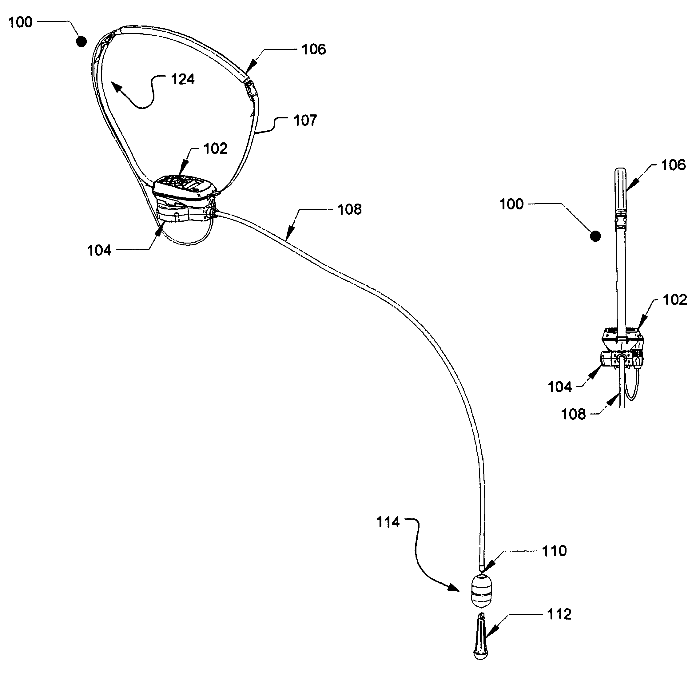
[0068]The present invention relates to a depth determination apparatus which may be used in a variety of applications. One particular, though non-limiting, application, is use of the apparatus to measure the depth of holes or shafts used in drilling and blasting operations, and this specific application will be used to describe the use of the apparatus. The apparatus could, however, be used in many other operations and to measure the depth / height of many other features. By way of non-limiting examples, the invention could be used to measure the height / depth of shafts, holes, pits, fissures, caves, crevasses, chasms, buildings, escarpments, waterfalls, etc. The invention may also be used in aquatic environments, for example to determine the depth of sea or river beds where relatively precise readings are required.

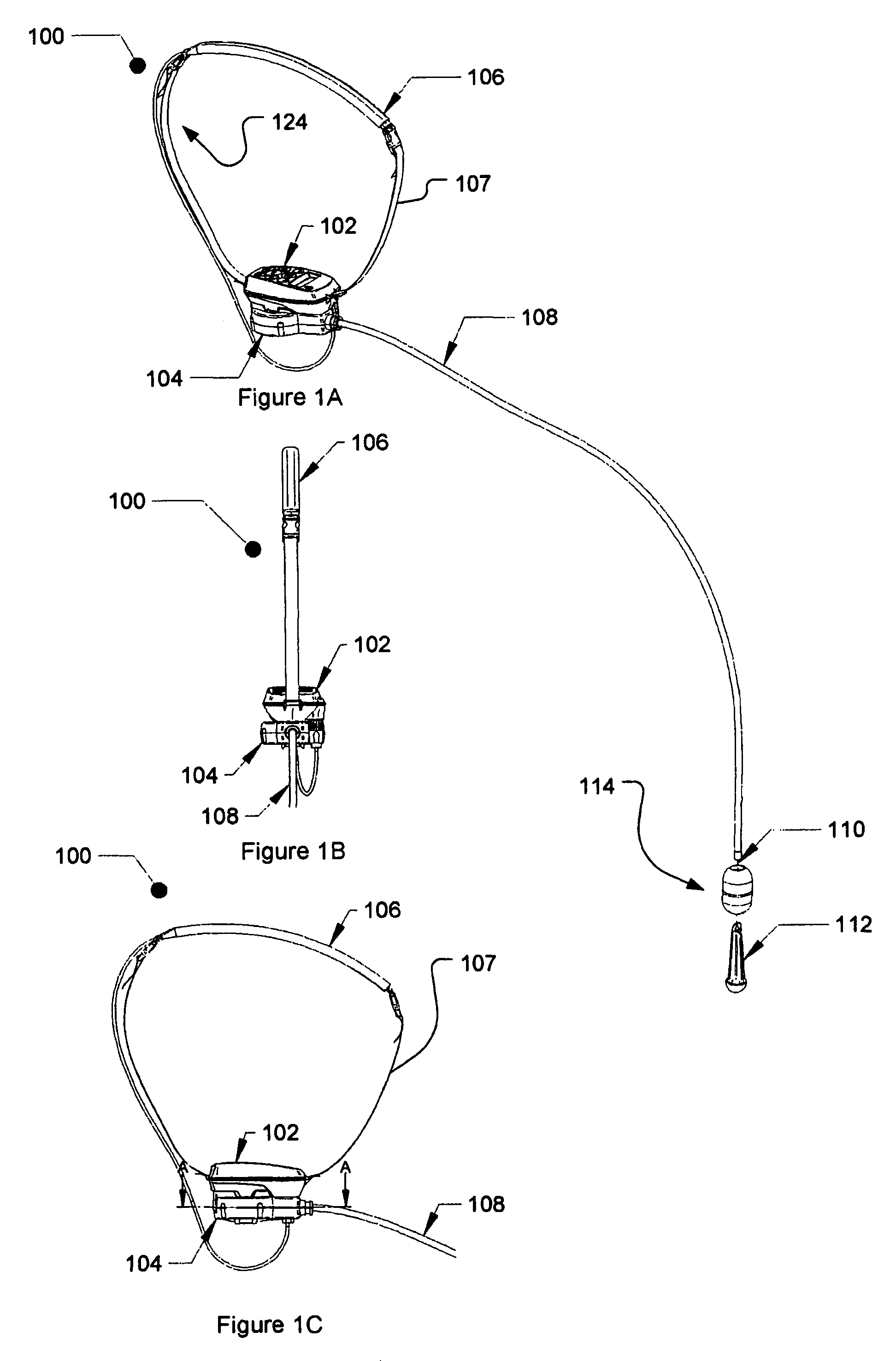
[0069]FIGS. 1A, 1B and 1C respectively provide a perspective, front elevation and side elevation view of a depth determination apparatus 100 in accordance with an embodiment...


PUM


Abstract

A depth determination apparatus is described. The depth determination apparatus includes a rotatable reel for receiving a length of line, a free end of the line being adapted to receive a weight, a hollow elongate leader assembly through which the line is played out and retracted, a measuring arrangement for measuring the length of line played out and / or retracted through the hollow elongate leader; and a drive means for at least retracting the line through the hollow elongate leader.

Description

PRIORITY CLAIM TO RELATED APPLICATIONS[0001]This application is a national stage application under 35 U.S.C, §371 of PCT / AU2010 / 001412, filed Oct. 22, 2010, and published as WO 2011 / 047440 A1 on Apr. 28, 2011, which claims priority to Australian Application No. 2009905193, filed Oct. 23, 2009, and to Australian Application No. 2010902586, filed Jun. 11, 2010, which applications and publication are incorporated herein by reference and made a part hereof in their entirety, and the benefit of priority of each of which is claimed herein.FIELD OF THE INVENTION[0002]The present invention relates to apparatus for determining the depth or height of a feature of interest. The apparatus is suitable for use in determining the depth of shafts or drill holes used in blasting operations, however can be used for determining the depth or height of other features.BACKGROUND OF THE INVENTION[0003]Many operations require the depth or height of a particular feature to be accurately determined. One such...

Claims


Application Information

Patent Timeline
Patent Type & Authority Patents(United States)
IPC IPC(8): G01B3/10F42D1/00F42D3/04G01B3/11G01F23/72
CPCG01B3/11F42D1/00F42D3/04G01F23/72
Inventor STEPHENS, PETER DAVEKUMARCOOK, GARY ALLAN
Owner IGUANA IND SOLUTIONS
Why Eureka
Try Eureka