Method and apparatus for determining parameters of linear motion in a surgical instrument

a technology of linear motion and measurement parameters, applied in the field of methods and equipment, can solve the problems of surgeon's hand fatigue, many sensors increase mechanical wear within the surgical instrument, and the size, length, diameter, weight, etc., and achieve the effect of reducing the mechanical wear of the components, minimizing the size of the surgical instrument, and simple sensor design

Active Publication Date: 2015-02-24
TYCO HEALTHCARE GRP LP
View PDF181 Cites 1492 Cited by
  • Summary
  • Abstract
  • Description
  • Claims
  • Application Information

AI Technical Summary

Benefits of technology

[0010]The present disclosure, in one aspect, features a surgical instrument. The surgical instrument includes a housing, an elongated shaft, a firing rod, a drive mechanism, a motion sensor, and a measurement unit. The elongated shaft extends distally from the housing and defines a first longitudinal axis. The firing rod is disposed within the elongated shaft and the drive mechanism is disposed at least partially within the housing. The drive mechanism mechanically cooperates with the firing rod. The motion sensor senses a change in the electric field between the firing rod and the elongated shaft. The measurement unit determines a parameter of the motion of the firing rod based on a sensed change in the electric field. Thus, in some embodiments, the surgical instrument simply includes a motion sensor electrically coupled to the firing rod to sense the electric field. This sensor design does not mechanically interact with the firing rod and thus reduces the mechanical wear of the components of the surgical instrument. In addition, this sensor design is simple and minimizes the size of the surgical instrument for optimum maneuverability during surgical procedures.

Problems solved by technology

Repeated use of these surgical instruments can cause fatigue in a surgeon's hand.
Rotational sensors as well as other existing types of sensors, however, contribute in a significant way to the size, length, diameter, weight, and complexity of a surgical instrument.
In addition, many of these sensors increase mechanical wear within the surgical instrument because the sensors mechanically interact with or repeatedly make physical contact with components of the surgical instrument.

Method used


Image

  • Method and apparatus for determining parameters of linear motion in a surgical instrument
  • Method and apparatus for determining parameters of linear motion in a surgical instrument
  • Method and apparatus for determining parameters of linear motion in a surgical instrument

Examples


Embodiment Construction

[0039]Embodiments of the presently disclosed surgical instrument are now described in detail with reference to the drawings, in which like reference numerals designate identical or corresponding elements in each of the several views. As used herein the term “distal” refers to that portion of the surgical instrument, or component thereof, farther from the user while the term “proximal” refers to that portion of the surgical instrument or component thereof, closer to the user.

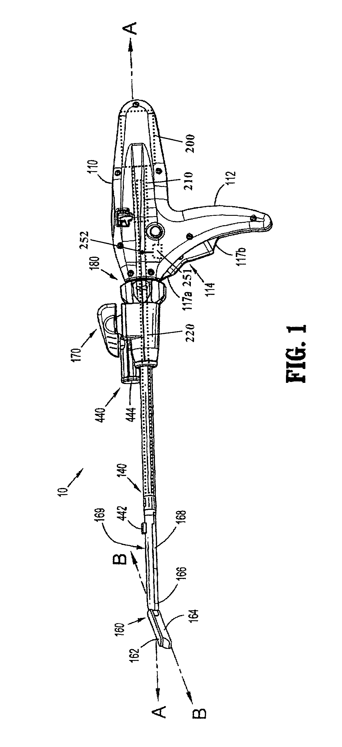
[0040]A surgical instrument (e.g., a powered surgical stapler) in accordance with the present disclosure is referred to in the figures as reference numeral 10. Referring initially to FIG. 1, powered surgical instrument 10 includes a housing 110, an elongated shaft 140 defining a first longitudinal axis A-A, and an end effector 160 that defines a second longitudinal axis B-B. The elongated shaft 140 extends distally from the housing 110 and the end effector 160 is disposed adjacent a distal portion of the elongate...


PUM

PropertyMeasurementUnit
period of timeaaaaaaaaaa
frequencyaaaaaaaaaa
frequencyaaaaaaaaaa

Abstract

A surgical instrument and method of controlling the surgical instrument are disclosed. The surgical instrument includes a housing and an elongated shaft that extends distally from the housing and defines a first longitudinal axis. The surgical instrument also includes a firing rod disposed in the elongated shaft and a drive mechanism disposed at least partially within the housing. The drive mechanism mechanically cooperates with the firing rod to move the firing rod. A motion sensor senses a change in the electric field (e.g., capacitance, impedance, or admittance) between the firing rod and the elongated shaft. The measurement unit determines a parameter of the motion of the firing rod, such as the position, speed, and direction of the firing rod, based on the sensed change in the electric field. A controller uses the measured parameter of the motion of the firing rod to control the drive mechanism.

Description

CROSS-REFERENCE TO RELATED APPLICATIONS[0001]This application claims the benefit of and priority to U.S. Provisional Patent Application Ser. No. 61 / 313,231, filed on Mar. 12, 2010, the entire contents of which are incorporated by reference herein. This application is also a Continuation-in-Part of U.S. patent application Ser. No. 12 / 189,834, filed on Aug. 12, 2008, which claims the benefit of, and priority to, U.S. Provisional Patent Application Ser. No. 60 / 997,854, filed on Oct. 5, 2007, the entire contents of which are incorporated by reference herein.BACKGROUND[0002]1. Technical Field[0003]The present disclosure relates to a method and apparatus for manipulating body tissue or deploying surgical fasteners into body tissue, and, in particular, to a method and apparatus for determining parameters of the motion of a firing rod in a surgical instrument based on an electric field associated with the firing rod.[0004]2. Background of Related Art[0005]Current surgical instruments typica...

Claims


Application Information

Patent Timeline
Patent Type & Authority Patents(United States)
IPC IPC(8): A61B17/068A61B17/00A61B17/072A61B19/00
CPCA61B17/07207A61B2017/00017A61B2017/00367A61B2017/00734A61B2019/467A61B2090/067A61B17/068
Inventor MCCUEN, DAVID M.
Owner TYCO HEALTHCARE GRP LP
Why Eureka
Try Eureka