
Remote monitoring system and method utilizing wireless network

a wireless network and monitoring system technology, applied in transmission systems, wireless architecture usage, instruments, etc., can solve the problems of inefficient technology for transmitting small amounts of data (microdata), cost prohibitive, and inefficient manufacturing solutions for manufacturers or distributors, so as to reduce manufacturing time and cost

Inactive Publication Date: 2015-02-24
SHREIBER MICHAEL A +1
View PDF3 Cites 10 Cited by
  • Summary
  • Abstract
  • Description
  • Claims
  • Application Information

AI Technical Summary

Benefits of technology

The patent describes a system that allows manufacturers to create multiple types of remote monitoring devices with the same data packaging and transmission module using a centralized data routing engine. This system reduces manufacturing time and expense because the data routing and dissemination functions are offloaded to a centralized service, allowing manufacturers to have complete control of the data's disposal without needing to interact with the remote monitoring device itself. The system also tracks the amount of data and bandwidth usage for each remote monitoring device, allowing manufacturers to efficiently streamline billing processes for activating thousands of remote monitoring devices.

Problems solved by technology

Currently, manufacturers or distributors do not have a cost effective solution for bringing wireless monitoring devices to market when the device needs to send only tiny amounts of data (microdata) because the use of standard cellular technology for transmitting small amounts of data (microdata) is inefficient and cost prohibitive due to a number of factors.

Method used


Image

  • Remote monitoring system and method utilizing wireless network
  • Remote monitoring system and method utilizing wireless network
  • Remote monitoring system and method utilizing wireless network

Examples


Embodiment Construction

[0022]Considering the drawings, wherein like reference numerals denote like parts throughout the various drawing figures, reference numeral 10 is directed to a remote monitoring system: apparatus and method.

[0023]System Overview

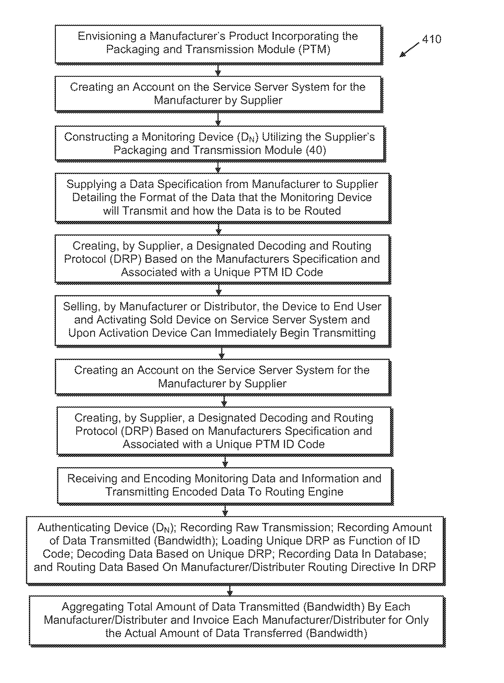
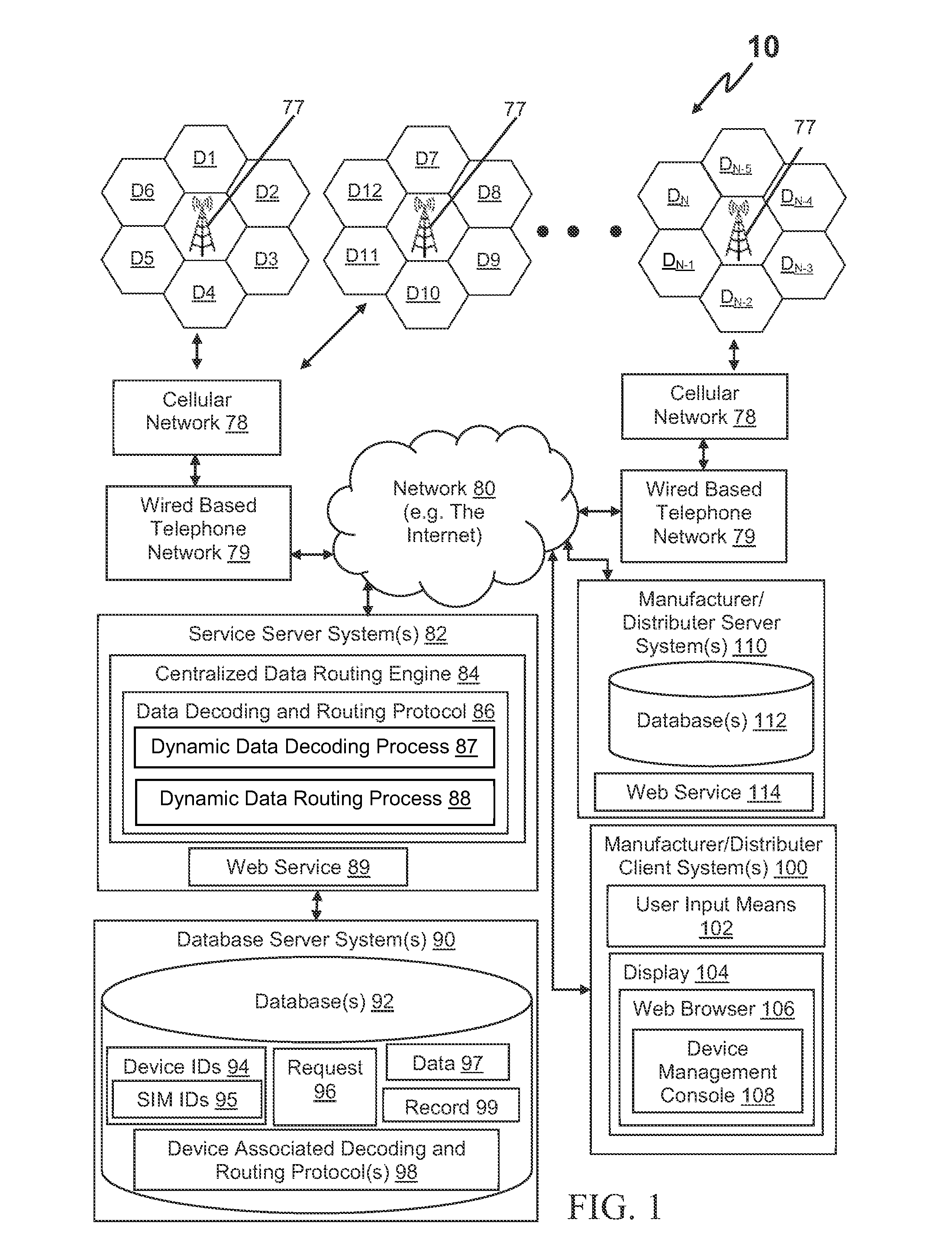
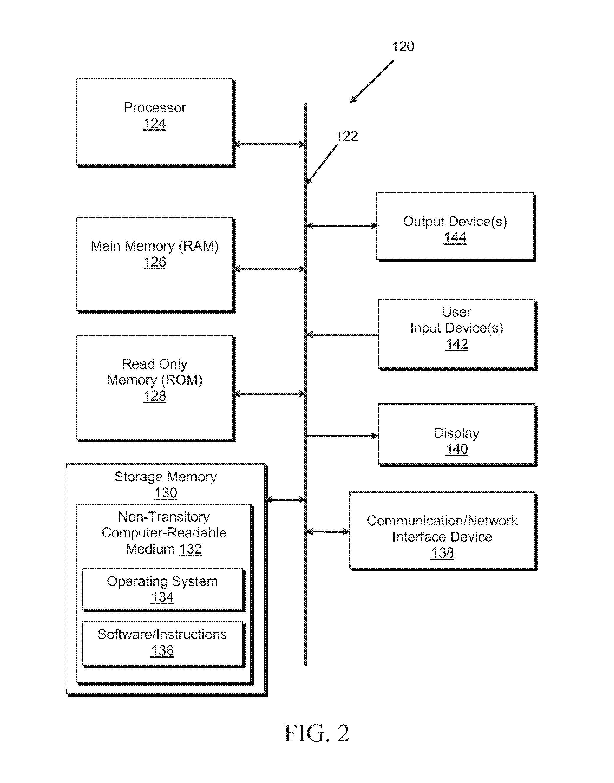
[0024]Referring to FIGS. 1 through 3, and in one embodiment, the remote monitoring system 10 is comprised of a plurality of remote monitoring devices D1 through DN operatively coupled to a service server system 82 by utilizing a cellular network 78 comprising one or more cellular tower / base station units 77. Each of the plurality of remote monitoring devices D1 through DN is comprised of a data packaging and transmission module (PTM) 40 operatively coupled to a monitoring module 58. The data packaging and transmission module (PTM) or device 40 packages data received from the monitoring module or device 20 into contiguous data blocks, packets, or packages 46 and wirelessly transmits the packages 46 to one or more of the ver / base station units 77 of the cellula...


PUM


Abstract

A remote monitoring system and method that packages, transmits, receives, decodes, stores, and distributes data sent from remote monitoring devices via a wireless network and that provides manufacturers with reduced wireless manufacturing expenses, data collection costs, dissemination costs, and wireless network access fees.

Description

CROSS-REFERENCE TO RELATED APPLICATIONS[0001]This application claims priority under 35 USC Section 119(e) to U.S. Provisional Patent Application No. 61 / 524,304, filed Aug. 16, 2011, the entire disclosure of which is incorporated herein by reference.FIELD OF THE INVENTION[0002]This invention relates generally to a remote monitoring system and method utilizing a wireless network and, in particular, to a remote monitoring system and method for packaging, transmitting, receiving, decoding, storing, and distributing data sent from remote monitoring devices via a wireless network.BACKGROUND OF THE INVENTION[0003]Currently, manufacturers or distributors do not have a cost effective solution for bringing wireless monitoring devices to market when the device needs to send only tiny amounts of data (microdata) because the use of standard cellular technology for transmitting small amounts of data (microdata) is inefficient and cost prohibitive due to a number of factors. These factors include:...

Claims


Application Information

Patent Timeline
Patent Type & Authority Patents(United States)
IPC IPC(8): H04M11/00G08C15/06G08C19/04H04W24/00H04M15/00
CPCH04Q2209/10H04Q2209/40H04Q9/00H04M15/44
Inventor SHREIBER, MICHAEL A.SHREIBER, RICHARD M.
Owner SHREIBER MICHAEL A
Features
  • Generate Ideas
  • Intellectual Property
  • Life Sciences
  • Materials
  • Tech Scout
  • Unparalleled Data Quality
  • Higher Quality Content
  • 60% Fewer Hallucinations
Learn More