Rotary steerable drilling apparatus and method

a rotary steerable, drilling technology, applied in drilling machines and methods, earth-moving drilling, directional drilling, etc., can solve the problems of high operating cost of platforms, complex well profiles, and inability to withstand the rotational torque required in drilling, so as to minimize the energy required and reduce the bending stiffness

Active Publication Date: 2015-03-03
SCHLUMBERGER TECH CORP
View PDF9 Cites 6 Cited by
  • Summary
  • Abstract
  • Description
  • Claims
  • Application Information

AI Technical Summary

Benefits of technology

[0007]The present invention is a steerable bottom hole assembly for use in a well bore made up, at a minimum, with a universal joint connectable to a drill string; a control bias unit connected to the universal joint; and, a drill bit connected to the control bias unit. A stabilizer can be placed adjacent the universal joint thereby minimizing the energy required by the bias pads to move the BHA from the well bore wall. Furthermore, in another embodiment, the stabilizer placed adjacent the universal joint can be undergauge. The universal joint of the present invention provides a low bending stiffness relative to the control bias unit and the drill string to which is attached thereby making the movement of the BHA independent from the movement of the balance of the drill string.

Problems solved by technology

Coiled tubing or flexible tubing may not withstand the rotational torque required in drilling.
This is especially true of offshore drilling platforms which have daily operating costs.
Such boreholes can provide very complex well profiles.
The force that may be asserted against the pads is generally limited by both the available pressure difference and the piston diameter.
Often, the hydraulic force available to push the pad into engagement with the well bore wall is insufficient to both lift the BHA and affixed drill string from the well bore wall and bend the BHA in the desired direction.

Method used


Image

  • Rotary steerable drilling apparatus and method
  • Rotary steerable drilling apparatus and method

Examples


Embodiment Construction

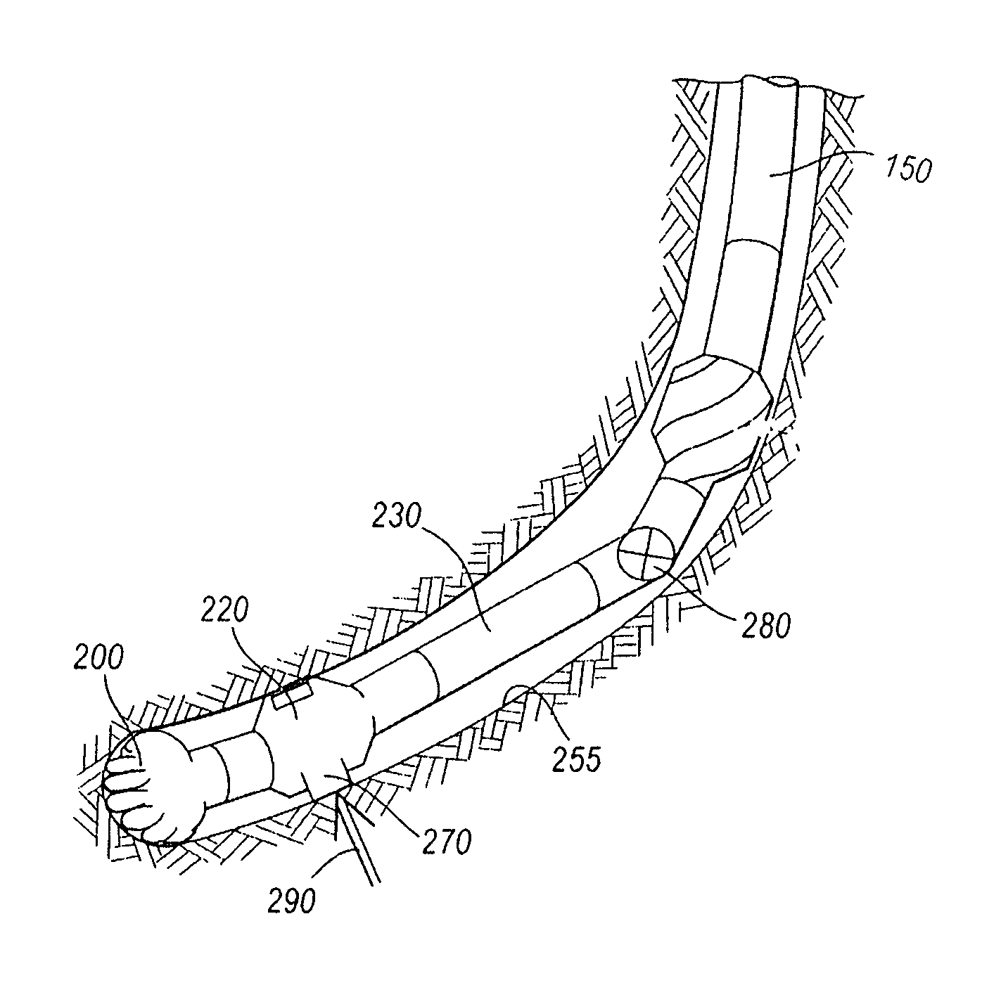
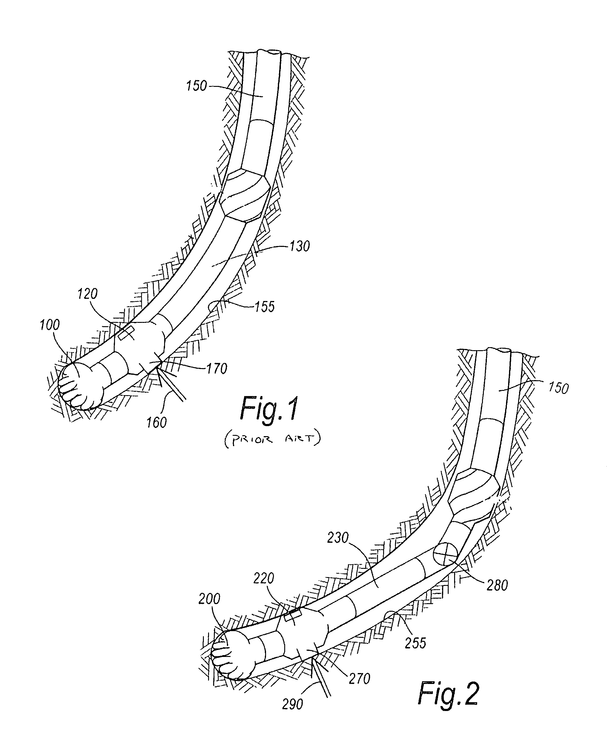
[0014]FIG. 1 shows a typical steerable BHA consisting of a drill bit 100 connected to a bias unit 120. Bias unit 120 operates during rotational drilling by moving actuator pads or pistons 170 into engagement with a bore hole wall 155 at a point or fulcrum 160 to move the drill bit 100 and bias unit 120 in a preferred direction as determined by the sensors located in control unit 130. The method of controlling a deviated well by activating a rotary steerable bias unit is more fully described in U.S. patent application Ser. No. 10 / 248,053, filed Dec. 13, 2002, and the patents cited therein, all of which are incorporated herein by reference.

[0015]As may be readily appreciated, when the unit is in the position shown in FIG. 1, the bias unit 120 can be required to lift the entire weight of the drill string and BHA off of the well bore wall. This can be a problem in unconsolidated and / or soft formations. Additionally, the bias unit 120 can be required to overcoming the flexural rigidity o...


PUM


Abstract

The present invention relates to a rotary steerable drilling apparatus which separates the drill string from the bottom hole assembly thereby allowing the biasing means to push the bit in a given direction without having to lift the drill string along with the bottom hole assembly.

Description

BACKGROUND OF THE INVENTION[0001]This invention relates generally to oilfield downhole tools and more particularly to a rotary steerable drilling apparatus utilizing a universal joint reducing the forces experienced by a bias unit in pushing the bit in the preferred drill path.[0002]To obtain hydrocarbons such as oil and gas, boreholes or wellbores are drilled by rotating a drill bit attached to the bottom of a bottom hole assembly (“BHA”). The drilling assembly is attached to the distal end of a drill string comprised of a plurality of tubulars or a relatively flexible spoolable tubing string commonly referred to as “coiled tubing.” The section comprising the tubing and the drilling assembly is generally referred to as the “drill string.” When a jointed pipe is used as the tubing, the drill bit is rotated by rotating the jointed pipe from the surface or by a mud motor attached to the tubing proximate the drill bit, or preferably both rotation and continuous directional drilling wit...

Claims


Application Information

Patent Timeline
Patent Type & Authority Patents(United States)
IPC IPC(8): E21B7/06
CPCE21B7/067E21B7/06E21B7/068
Inventor DOWNTON, GEOFFSMITH, DAVID L.
Owner SCHLUMBERGER TECH CORP
Why Eureka
Try Eureka