Mechanical coolant pump

Active Publication Date: 2015-03-03
PIERBURG PUMP TECH
View PDF11 Cites 1 Cited by
  • Summary
  • Abstract
  • Description
  • Claims
  • Application Information

AI Technical Summary

Benefits of technology

The invention is a coolant pump for internal combustion engines that includes a main pump body, a rotating pump wheel with an axial inlet opening, and a valve disk that can be opened or closed to control the flow of coolant. The pump is designed so that the valve can be closed without creating any flow resistance, making it a highly efficient coolant pump. The valve can be controlled by an actuator and can be used with different types of combustion engines without needing a separate housing. The valve is attached to a disk shaft and can be opened or closed with a simple electromagnetic coil. The pump also includes a cylindrical recess that guides the disk shaft and allows for easy shifting of the valve between its open and closed positions. The invention solves the problem of high flow resistance in conventional coolant pumps and provides a more efficient and controllable solution for combustion engines.

Problems solved by technology

This flow resistance causes turbulence in the coolant flow so that the energy consumption of the pump is high even when the pump is pumping with a minimal flow rate.

Method used


Image

  • Mechanical coolant pump
  • Mechanical coolant pump
  • Mechanical coolant pump

Examples


Embodiment Construction

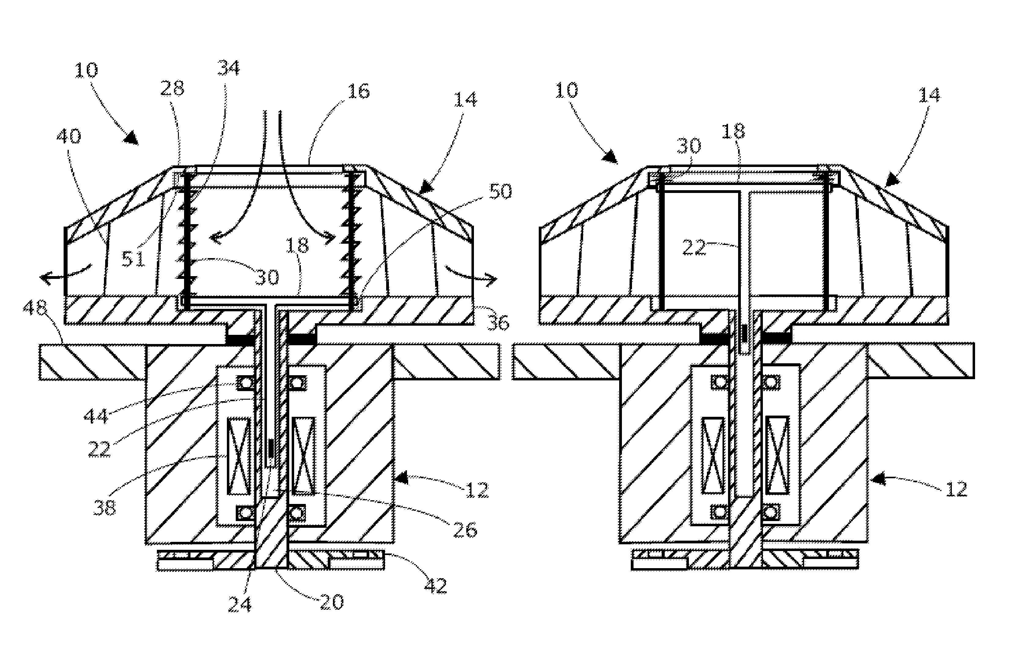
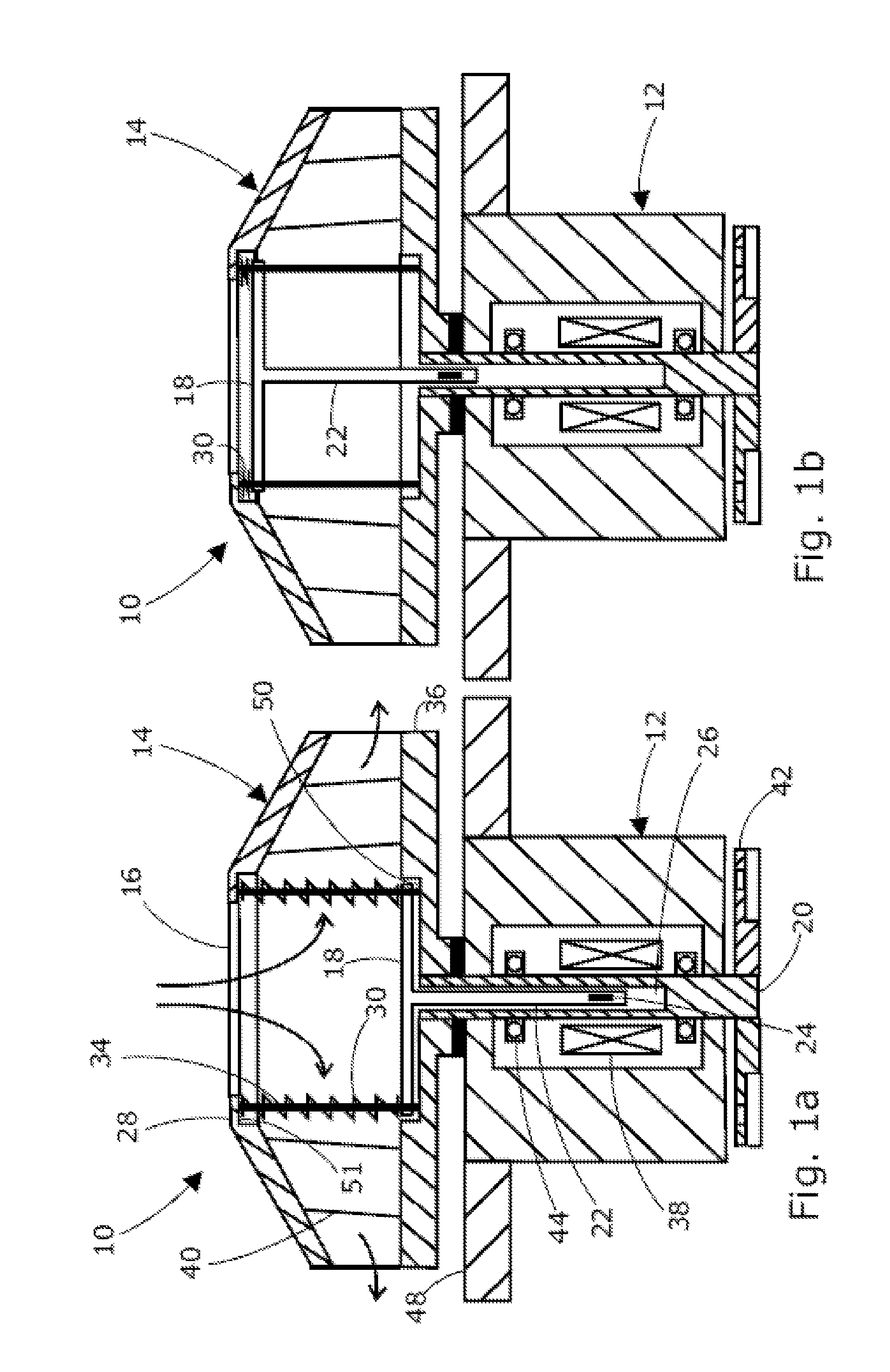
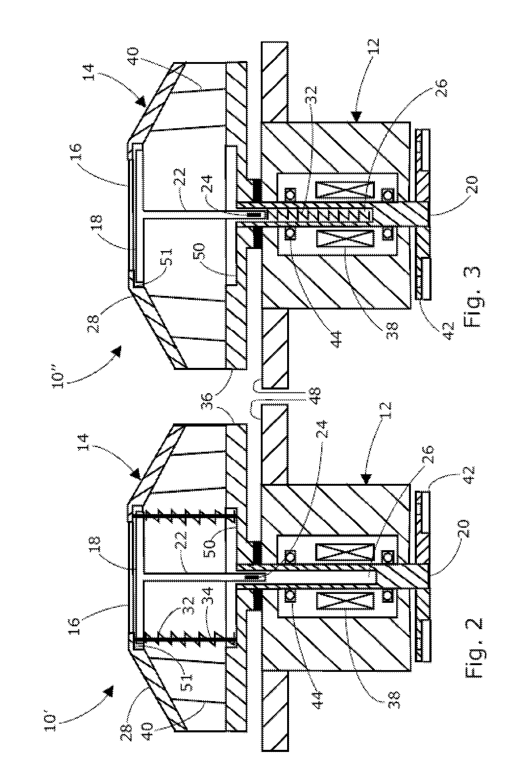
[0011]The mechanical coolant pump for an internal combustion engine according to the present invention comprises a stationary main pump body and a pump wheel rotatably supported by the main pump body. The pump wheel is an impeller which comprises a base disk and pump blades. The coolant pump is provided with a central axial inlet opening. The pump wheel pumps the coolant from the inlet opening radially outwardly. The pump wheel is provided with an axially shiftable valve disk being actuated by an actuator and closing the axial inlet opening in the closed position of the valve disk, i.e., the distal valve disk position. In the open valve disk position, the valve disk is positioned at the proximal axial end of the pump wheel.

[0012]The fact that the pump wheel is rotatably supported by the main pump body in combination with the axial inlet opening which is closable by the axially shiftable valve disk provides a coolant pump with a minimized flow resistance, especially without a flow re...


PUM


Abstract

A mechanical coolant pump for an internal combustion engine includes a main pump body configured to be stationary. A pump wheel is rotatably supported by the main pump body. The pump wheel comprises a central axial inlet opening. The pump wheel is configured to pump a coolant from the central axial inlet opening radially outwardly. A valve disk configured to be axially shiftable is arranged in the pump wheel. An actuator is configured to actuate the valve disk so as to close the central axial inlet opening in a closed position of the valve disk.

Description

CROSS REFERENCE TO PRIOR APPLICATIONS[0001]This application is a U.S. National Phase application under 35 U.S.C. §371 of International Application No. PCT / EP2010 / 051706, filed on Feb. 11, 2010. The International Application was published in English on Aug. 18, 2011 as WO 2011 / 098126 A1 under PCT Article 21(2).FIELD[0002]The present invention relates to a mechanical coolant pump for an internal combustion engine.BACKGROUND[0003]A mechanical coolant pump is a coolant pump which is driven by the combustion engine, for example, by using a driving belt driving a driving wheel of the pump. As long as the combustion engine is cold, only a minimum coolant flow is needed. Therefore, mechanical coolant pumps are used which can vary the capacity of the coolant flow rate. As long as the combustion engine is cold, the flow rate is minimized, with the result that the combustion engine warming-up phase is shortened.[0004]A mechanical coolant pump of the prior art which is able to vary the capacity...

Claims


Application Information

Patent Timeline
IPC IPC(8): F04D15/02F04D15/00
CPCF04D15/0038F05D2270/62F05D2270/64
Inventor DURAND, JEAN-MICHELBROEMMEL, ACHIM
Owner PIERBURG PUMP TECH
Why Eureka
Try Eureka