
Method and apparatus for restricting flow through an opening in the side wall

a technology of side wall and opening, which is applied in the field of medical procedures and apparatus, can solve the problems of life-threatening aneurysms, rapid and uncontrolled loss of blood, and ballooning of the side wall of the blood vessel

Active Publication Date: 2015-03-03
CORNELL UNIVERSITY
View PDF193 Cites 5 Cited by
  • Summary
  • Abstract
  • Description
  • Claims
  • Application Information

AI Technical Summary

Benefits of technology

The present invention provides a new and improved device for treating an aneurysm in a blood vessel, which can be delivered endoluminally and positioned within the blood vessel adjacent to the aneurysm while maintaining substantially normal blood flow through the blood vessel. The device comprises a single closed loop of elastic filament that can be expanded and contracted for movement and positioning within the blood vessel. The device has a flow-restricting face that can cover the mouth of the aneurysm and obstruct blood flow to the aneurysm, causing it to thrombose and close off. The device can be delivered using an inserter and can be expanded and contracted using a movable mount. The technical effect of this invention is to provide a minimally-invasive and effective treatment for an aneurysm that can maintain normal blood flow through the blood vessel.

Problems solved by technology

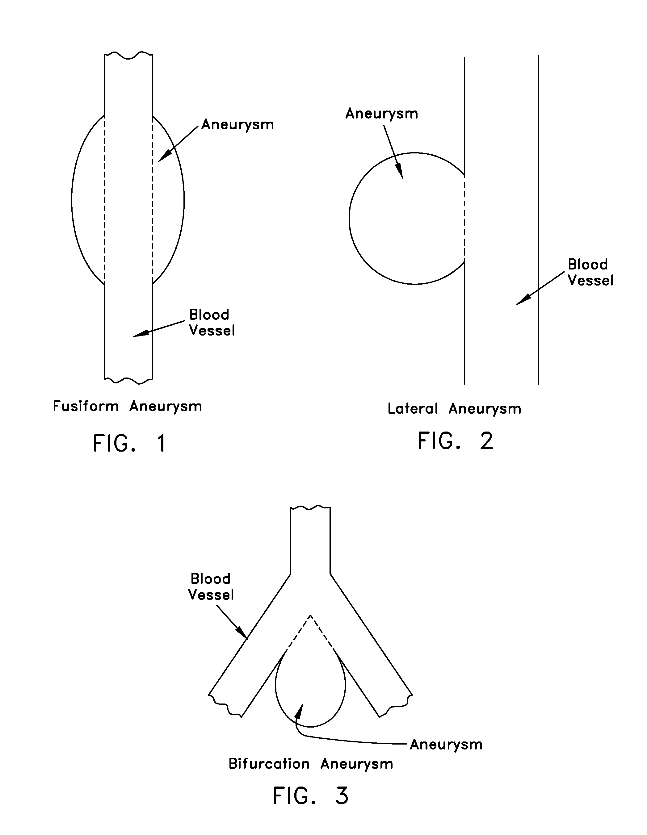
In some cases, a blood vessel can become weakened, thereby causing the side wall of the blood vessel to balloon outwardly so as to create an aneurysm.
Aneurysms can present a serious threat to the patient, since they may enlarge to the point of rupture, thereby resulting in a rapid and uncontrolled loss of blood.
Depending upon the size and location of the aneurysm, the aneurysm can be life-threatening.
However, this coil-depositing procedure has a number of drawbacks, including the risk of coil herniation into the lumen of the blood vessel; the risk of coil migration out of the aneurysm and into the blood vessel, with subsequent downstream migration; the risk of aneurysm rupture; etc.

Method used


Image

  • Method and apparatus for restricting flow through an opening in the side wall
  • Method and apparatus for restricting flow through an opening in the side wall
  • Method and apparatus for restricting flow through an opening in the side wall

Examples


Embodiment Construction

The Novel Expandable Spherical Structure in General

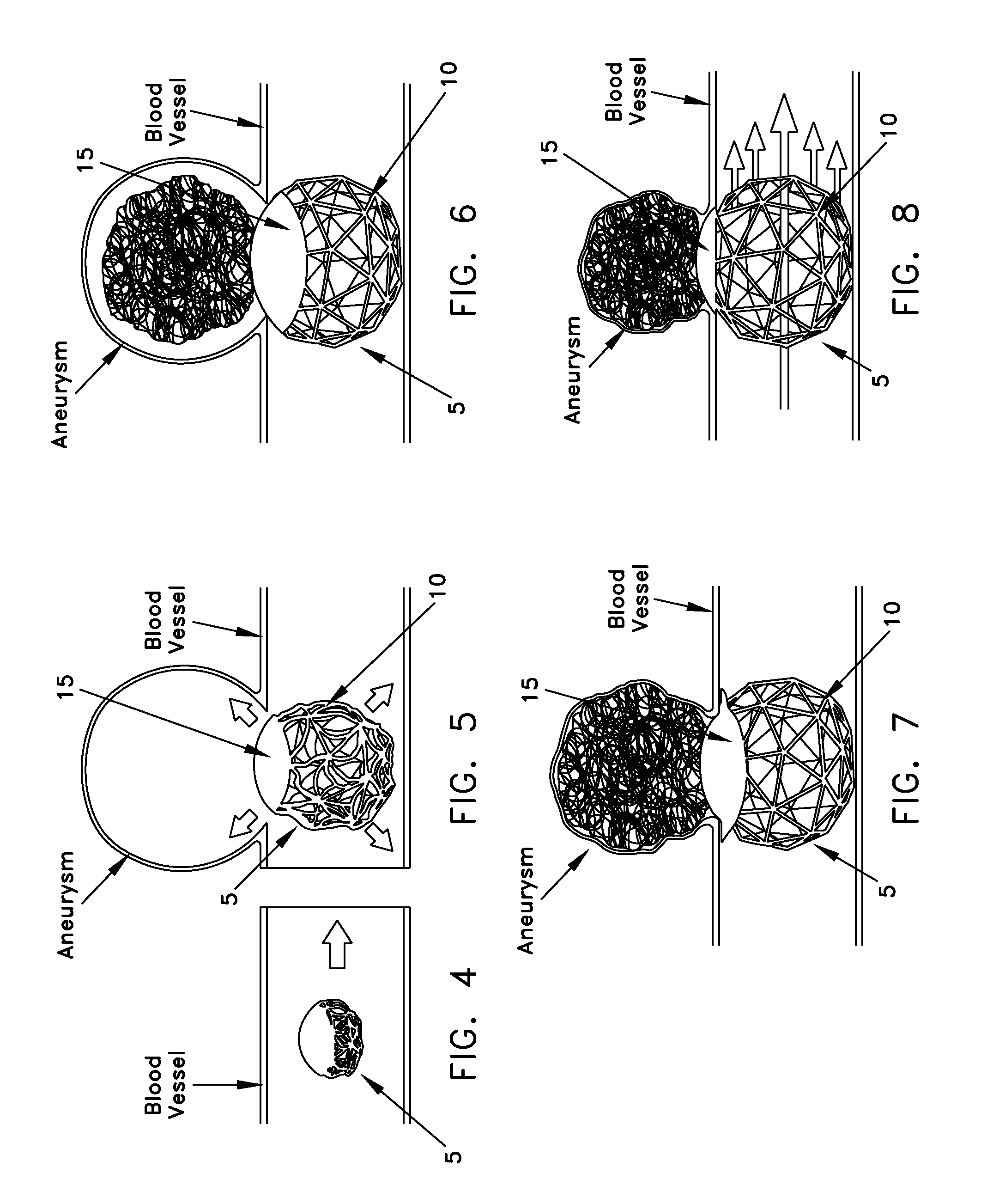
[0074]Looking now at FIGS. 4-8, there is shown a novel expandable spherical structure 5 formed in accordance with the present invention. Expandable spherical structure 5 is adapted for minimally-invasive, endoluminal delivery into a blood vessel or other body lumen, for restricting flow through an opening in the side wall of the blood vessel or other body lumen, and / or for reinforcing a weakness in the side wall of the blood vessel or other body lumen, while still maintaining substantially normal flow through the blood vessel or other body lumen.

[0075]Expandable spherical structure 5 generally comprises a spherical body comprising an open frame 10 with a flow-restricting face 15 (i.e., a closed face or a face having a high strut density). Preferably open frame 10 and flow-restricting face 15 together define the entire exterior shape of the spherical body, with open frame 10 making up the majority of the exterior shape of the spheric...


PUM


Abstract

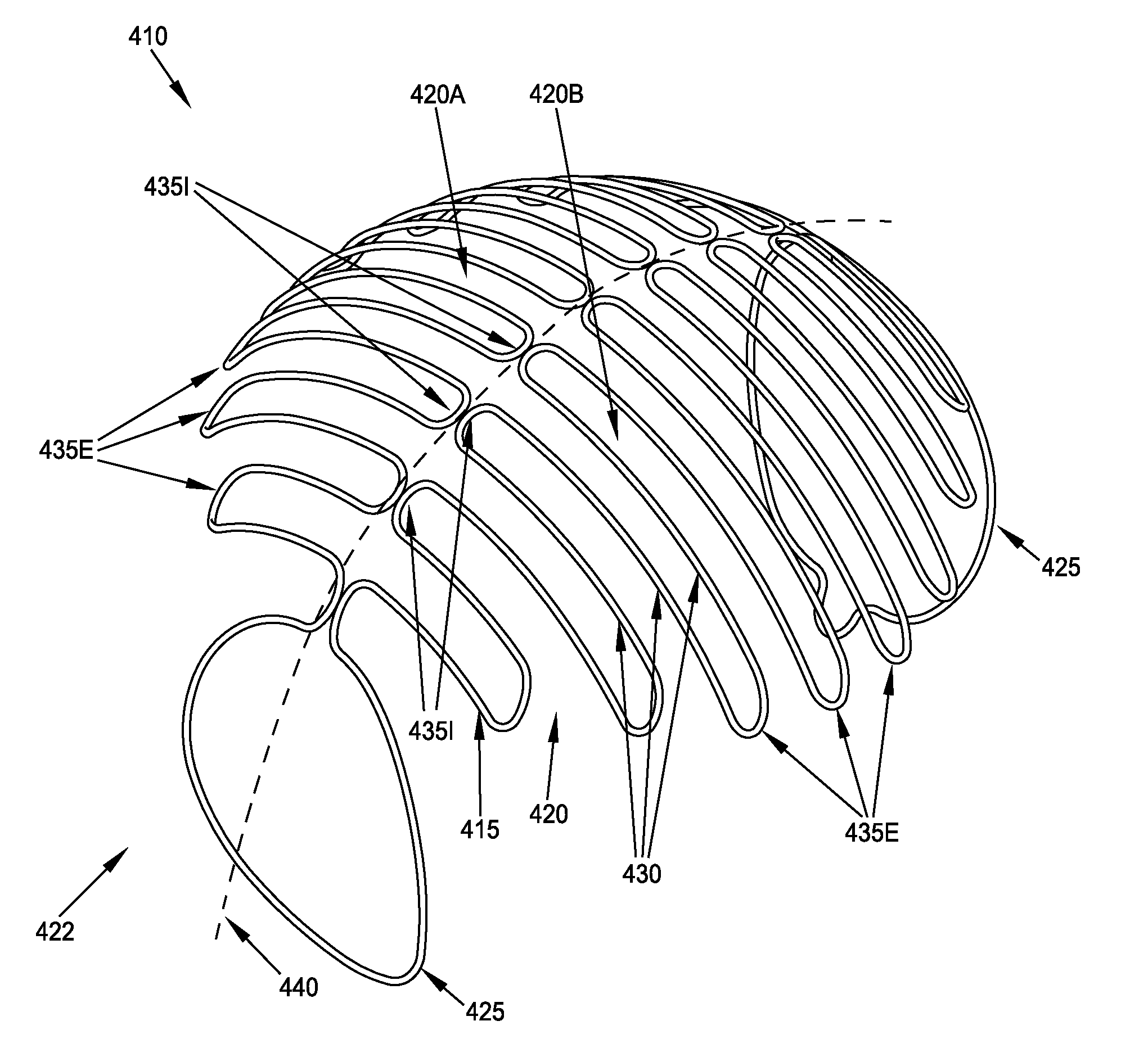
A device comprising a single closed loop of elastic filament configurable between (i) a first configuration for movement along a blood vessel; and (ii) a second configuration for lodging within a blood vessel, the second configuration providing a single flow-restricting face sized and configured to cover the mouth of the aneurysm and obstruct blood flow to the aneurysm while permitting substantially normal blood flow through the blood vessel, with the degree of obstruction at the mouth of the aneurysm being such that the aneurysm thromboses when the face is positioned over the aneurysm, the flow-restricting face comprising a plurality of lengths of the closed loop of filament disposed in close proximity to one another in a switchback configuration, and at least one leg for holding the flow-restricting face adjacent the mouth of the aneurysm, the leg configured so as to maintain substantially normal blood flow through the blood vessel.

Description

REFERENCE TO PENDING PRIOR PATENT APPLICATIONS[0001]This patent application:[0002](i) is a continuation-in-part of prior U.S. patent application Ser. No. 12 / 657,598, filed Jan. 22, 2010 by Howard Riina et al. for METHOD AND APPARATUS FOR RESTRICTING FLOW THROUGH AN OPENING IN THE SIDE WALL OF A BODY LUMEN, AND / OR FOR REINFORCING A WEAKNESS IN THE SIDE WALL OF A BODY LUMEN, WHILE STILL MAINTAINING SUBSTANTIALLY NORMAL FLOW THROUGH THE BODY LUMEN, which patent application: (a) is a continuation-in-part of prior U.S. patent application Ser. No. 12 / 332,727, filed Dec. 11, 2008 by Howard Riina et al. for METHOD AND APPARATUS FOR SEALING AN OPENING IN THE SIDE WALL OF A BODY LUMEN, AND / OR FOR REINFORCING A WEAKNESS IN THE SIDE WALL OF A BODY LUMEN, WHILE MAINTAINING SUBSTANTIALLY NORMAL FLOW THROUGH THE BODY LUMEN, which in turn claims benefit of prior U.S. Provisional Patent Application Ser. No. 61 / 007,189, filed Dec. 11, 2007 by Howard Riina et al. for DEPLOYABLE BLOCKING SPHERE; (b) cl...

Claims


Application Information

Patent Timeline
Patent Type & Authority Patents(United States)
IPC IPC(8): A61F2/06A61B17/00A61B17/12A61F2/30A61F2/82A61F2/86A61F2/91A61F2/95
CPCA61B17/12113A61B17/12022A61B17/12118A61B17/12131A61B17/1214A61B17/12172A61F2/86A61B2017/00867A61B2017/00871A61F2/82A61F2/91A61F2/95A61F2002/30242A61F2002/823A61F2002/9505A61F2230/0071A61B2017/12054A61F2230/005A61F2230/0091A61F2230/0095
Inventor RIINA, HOWARDMILSOM, JEFFREYCORNHILL, J. FREDERICKSMITH, KEVIN THOMASNGUYEN, TUAN ANHSCHNEIDER, DARRENDILLON, CHRISTOPHERGREELEY, GABRIELGUPTA, RAINUKAVAN HILL, JEREMYJOHNSTON, LESLIEDENARDO, MATTHEWSATHE, RAHUL
Owner CORNELL UNIVERSITY
Learn More