Operator induced oscillation filter to prevent instability from operator

a technology of oscillation filter and operator, which is applied in the field of control systems, can solve problems such as vibrations that may be perceptible in the operator cab, and achieve the effect of accelerating the rate of increase in the profile amplitud

Active Publication Date: 2015-03-03
CATERPILLAR INC
View PDF3 Cites 13 Cited by
  • Summary
  • Abstract
  • Description
  • Claims
  • Application Information

AI Technical Summary

Benefits of technology

[0015]In an embodiment, a profile of filter outputs over time may smooth spikes that occur in the historical trend, and allow a faster rate of increase in profile amplitudes than rate of decrease.

Problems solved by technology

During some operations of a machine, vibrations may be perceptible in the operator cab, and specifically, in the handle of a joystick or other manual control device.
Such vibrations may be the result of travel of the machine over uneven terrain, vibration of a work implement that is transferred to the cab and other vibration sources.

Method used


Image

  • Operator induced oscillation filter to prevent instability from operator
  • Operator induced oscillation filter to prevent instability from operator
  • Operator induced oscillation filter to prevent instability from operator

Examples


Embodiment Construction

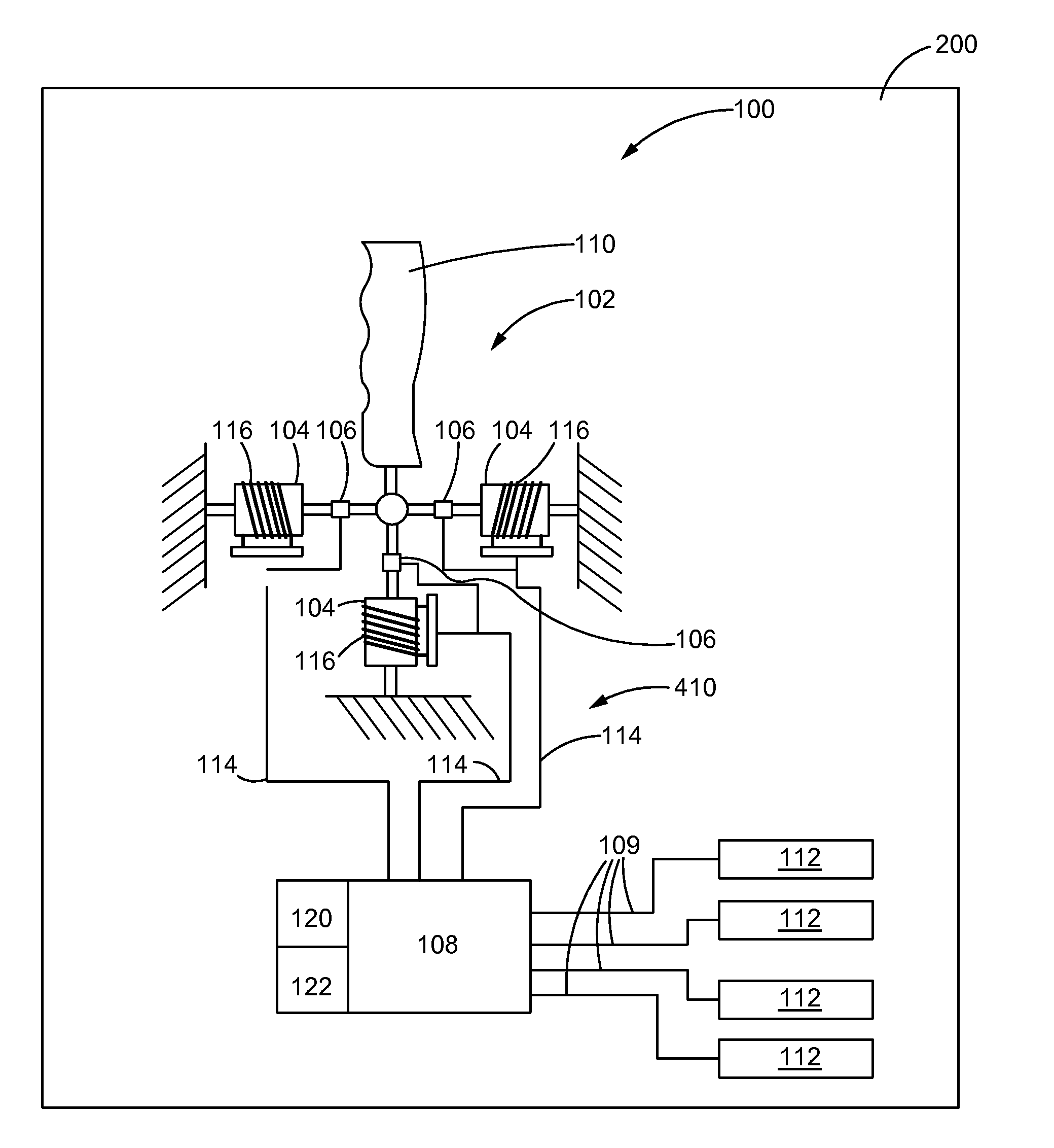
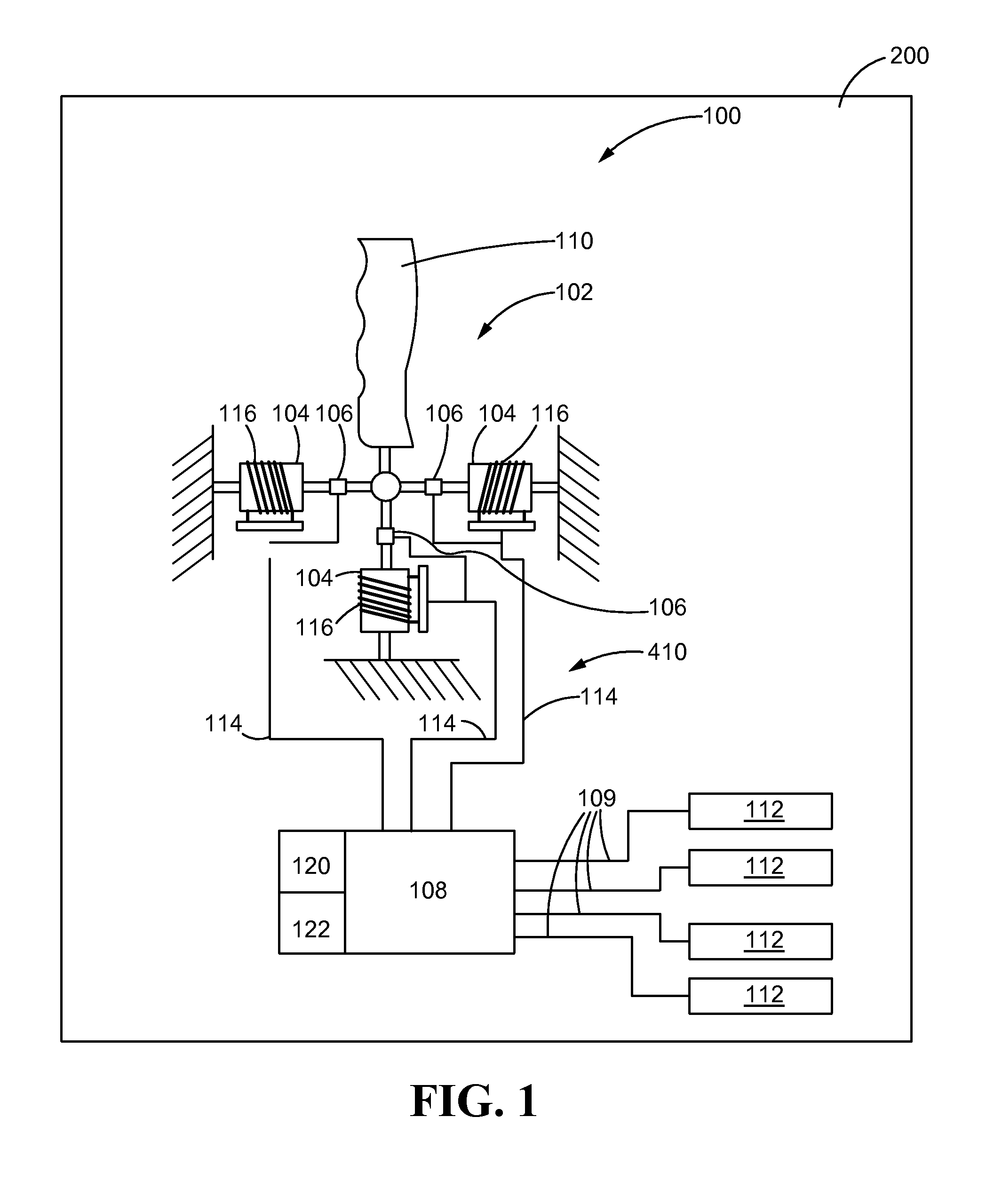
[0026]Referring now to the drawings, and with specific reference to FIG. 1, there is shown a control system in accordance with the present disclosure and generally referred to by reference numeral 100. The control system 100 may comprise a manual input device 102, a variable damper 104, one or more sensors 106, and at least one controller 108.

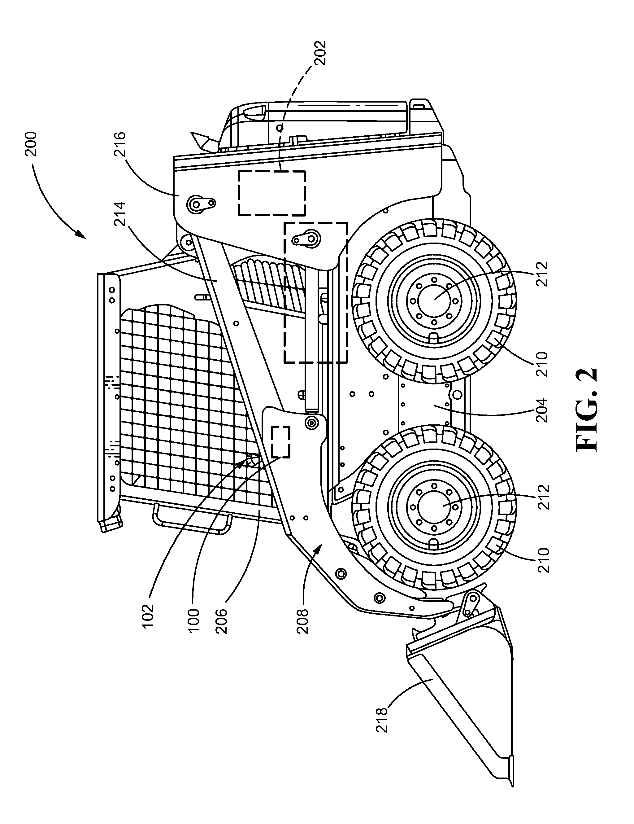
[0027]This disclosure describes an exemplary embodiment of the control system 100. While the exemplary embodiment of the control system 100 is described relative to a machine having a work implement for which operation of the work implement may be carried out by the selective control of actuators that are responsive to command signals from the controller, the teachings of this disclosure may be employed on other machines, including, but not limited to, machines without work implements, machines used for transportation, buses, trains, and wheelchairs.

[0028]While the following detailed description and drawings are made with reference to the contr...


PUM


Abstract

A system for controlling manual input device damping, and a related method and computer program product are disclosed. The system may comprise a manual input device mounted on a machine, a sensor that transmits to a controller an input signal indicative of the motion, acceleration, and/or deceleration of the machine, a variable damper that selectively alters the resistance of the input device to displacement based on a command signal transmitted by the controller, and a controller configured to adjust the resistance of the input device by adjusting the damping provided by the variable damper based on filtering of a historical trend of oscillation amplitudes at a frequency of concern.

Description

TECHNICAL FIELD[0001]The present disclosure generally relates to control systems and, more particularly, for control systems for use on machines to adjust the resistance to movement of manual control devices.BACKGROUND[0002]Machines are typically controlled by a combination of control devices. For example, an operator may use one device to move the machine into a desired direction, for example, a steering wheel or yolk, a different device to accelerate and decelerate the machine, for example, joystick, pedals or levers, and another device, for example, a joystick, to operate an implement of the machine, such as a bucket or shovel.[0003]Currently, machines such as skid steer loaders, excavators, cranes, wheel loaders, and the like, use joystick-type control devices to control the motion of their implements or the speed of the machine. These joysticks may have two, three or more degrees of freedom of motion, each of which corresponds to a particular direction or type of motion of the ...

Claims


Application Information

Patent Timeline
Patent Type & Authority Patents(United States)
IPC IPC(8): G06F19/00G06F3/0338
CPCG06F3/0338E02F9/2012
Inventor ELLIOTT, CHRISTOPHER
Owner CATERPILLAR INC
Why Eureka
Try Eureka