
Turbomachine compressor

a compressor and turbine technology, applied in the direction of machines/engines, stators, liquid fuel engines, etc., can solve the problems of specific consumption, degrading the compressor efficiency, affecting the performance of the engine, etc., and achieve the effect of simple, effective and economical

Active Publication Date: 2015-03-10
SN DETUDE & DE CONSTR DE MOTEURS DAVIATION S N E C M A
View PDF12 Cites 2 Cited by
  • Summary
  • Abstract
  • Description
  • Claims
  • Application Information

AI Technical Summary

Benefits of technology

This invention provides a simple and effective solution to improve the performance of turbomachines at low or intermediate speeds. It achieves this by allowing air to be bled from the compressor duct, using the flow rate of air bleed to modulate the air flow through the blade's orifices. This results in a reduction of air separations on the blades, thereby improving the efficiency of the turbomachine. The bleeding of air can occur at the external or internal mounting plates of each blade, and can also be done on both plates to avoid air separation on the blade's airfoil section.

Problems solved by technology

However, the geometry of these bleeds is generally fixed and, although the bleed is beneficial to given operating conditions of the compressor, its continuous presence, including under conditions where it is not necessary, can affect the performance of the engine (by degrading the efficiency of the compressor and thus the specific consumption).
In addition, a fixed bleed geometry limits the optimization capacities of the surge margin of a compressor.

Method used


Image

  • Turbomachine compressor
  • Turbomachine compressor
  • Turbomachine compressor

Examples


Embodiment Construction

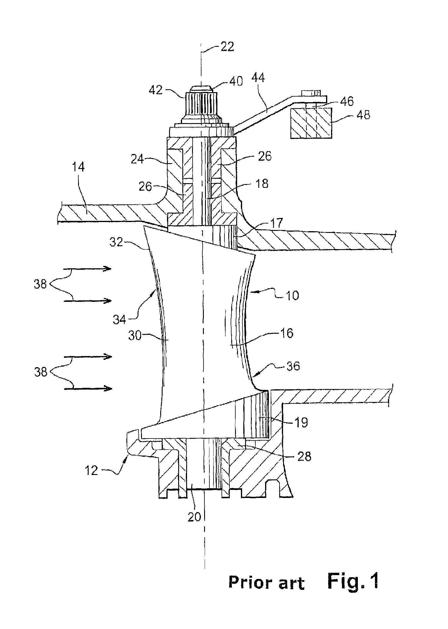
[0028]Reference is first made to FIG. 1, which shows a stator stage of variable-pitch blades 10 of a high-pressure turbomachine compressor, these blades 10 being distributed regularly around the longitudinal axis of the turbomachine and extending approximately radially between an internal casing 12 and an external casing 14 of the compressor.

[0029]Each blade 10 comprises an airfoil section 16 connected at its radially external end to a radial cylindrical pivot 18 by a first mounting plate 17 and at its radially internal end to a radial cylindrical pivot 20 by a second mounting plate 19, the internal pivot 20 and the external pivot 18 defining the rotational axis 22 of the blade.

[0030]The external cylindrical pivot 18 is engaged in a cylindrical hollow shaft 24 in the external casing 14 and is guided in rotation in this hollow shaft by cylindrical rings 26. The internal cylindrical pivot 20 is engaged in a cylindrical housing in the internal casing 12 and is guided in rotation in thi...


PUM


Abstract

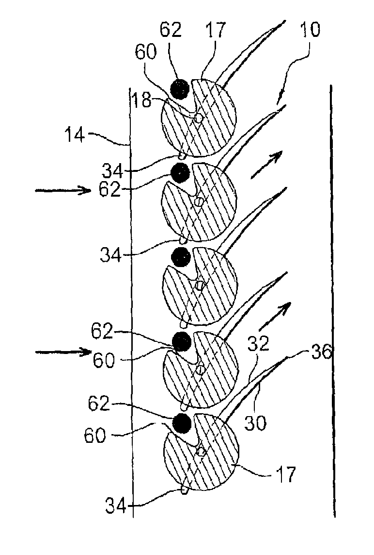
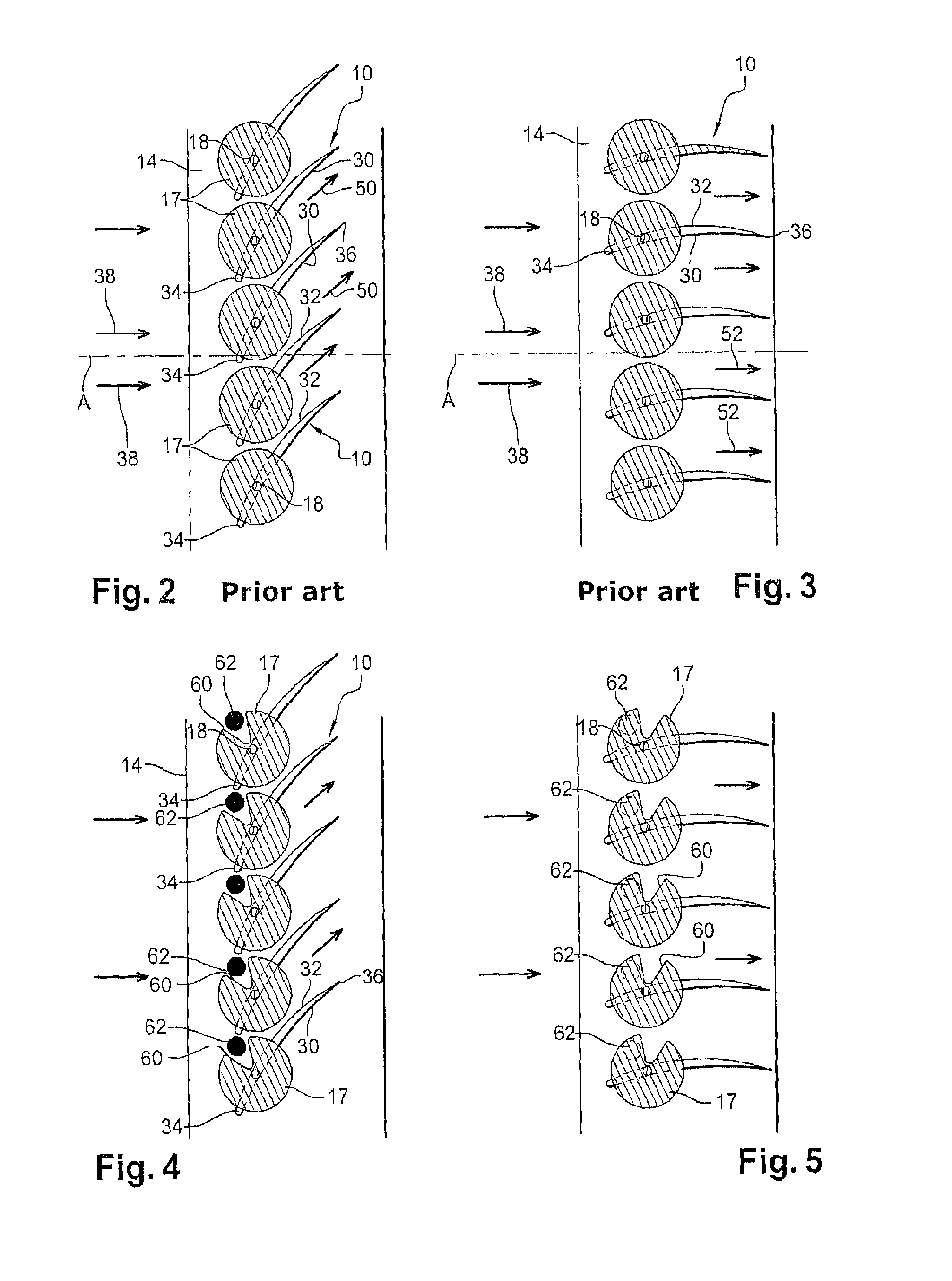
A turbomachine compressor including variable-pitch vanes including an aerofoil section connected by a mounting plate of circular outline to a pivot guided in rotation in an orifice in a casing is disclosed. The mounting plate of the vane includes at least one notch for bleeding air from the compressor stream. The notch is intended to communicate with a hole in the casing in order to remove the air bled off when the vanes are in a first position, and to be closed off by this casing when the vanes are in a second position, so that the flow rate of bled air depends on the pitch angle of the vanes.

Description

BACKGROUND OF THE INVENTION[0001]1. Field of the Invention[0002]The present invention relates to a turbomachine compressor such as a turbojet engine or an airplane turboprop engine, comprising at least one stator stage formed by variable-pitch blades.[0003]2. Description of the Related Art[0004]A stator stage of a compressor of this type comprises an annular row of variable-pitch stator blades which are carried by an external casing of the compressor. Each blade comprises an airfoil section which is connected at its radially external end to a radial cylindrical pivot by a mounting plate having an approximately circular contour, said pivot defining the rotational axis of the blade and being guided in rotation in a corresponding orifice in the external casing. The radially internal end of the airfoil section of each blade generally comprises a second cylindrical pivot extending along the rotational axis of the blade and guided in rotation in an orifice in an internal casing of the com...

Claims


Application Information

Patent Timeline
Patent Type & Authority Patents(United States)
IPC IPC(8): F04D29/68F01D17/16F02C6/08F04D27/02F04D29/56
CPCF04D29/563F01D17/162F02C6/08F04D27/023F04D29/682F05D2270/101Y10S415/914F04D27/0215
Inventor DOMERCQ, OLIVIER STEPHANEPERROT, VINCENT PAUL GABRIEL
Owner SN DETUDE & DE CONSTR DE MOTEURS DAVIATION S N E C M A
Learn More