Roofing shingle system and shingles for use therein

a technology for roofing shingles and roofing materials, which is applied in the direction of roofs, roof coverings, roofs, etc., can solve the problems of affecting transportation costs, leakage of shingles in the region where the shingles are made, and the cost of petroleum-based materials such as asphalt, so as to reduce the amount of material required to make shingles from a sheet of roofing material

Active Publication Date: 2015-03-17
BMIC LLC
View PDF24 Cites 16 Cited by
  • Summary
  • Abstract
  • Description
  • Claims
  • Application Information

AI Technical Summary

Benefits of technology

[0021]The width dimensions of the shingles operate to provide sufficient headlap overlap laterally proximate the openings in the buttlap portion of the subsequently installed shingle while reducing the material required to make the shingles by reducing the headlap overlap not laterally proximate the openings in the buttlap portion of the subsequently installed shingle.
[0024]In a further preferred embodiment, the amount of material required to make shingles from a sheet of roofing material is reduced by cutting the sheet of roofing material longitudinally along non-straight lines wherein the formed shingles have a cumulative maximum combined width that is greater than the width of the sheet of roofing material.

Problems solved by technology

Thus, when the shingles are exposed to wet weather, it is possible that leakage can occur at the region where the shingles abut.
As energy costs rise, the cost of petroleum-based materials, such as asphalt, and transportation expenses often rise as well.
The amount of material employed in a shingle can contribute to costs of the shingle and the overall weight of the shingle, which also affects transportation costs.

Method used


Image

  • Roofing shingle system and shingles for use therein
  • Roofing shingle system and shingles for use therein
  • Roofing shingle system and shingles for use therein

Examples


Embodiment Construction

[0036]The preferred embodiments of the present invention and its advantages are best understood by referring to FIGS. 1 through 9, like numerals being used for like and corresponding parts of the various drawings.

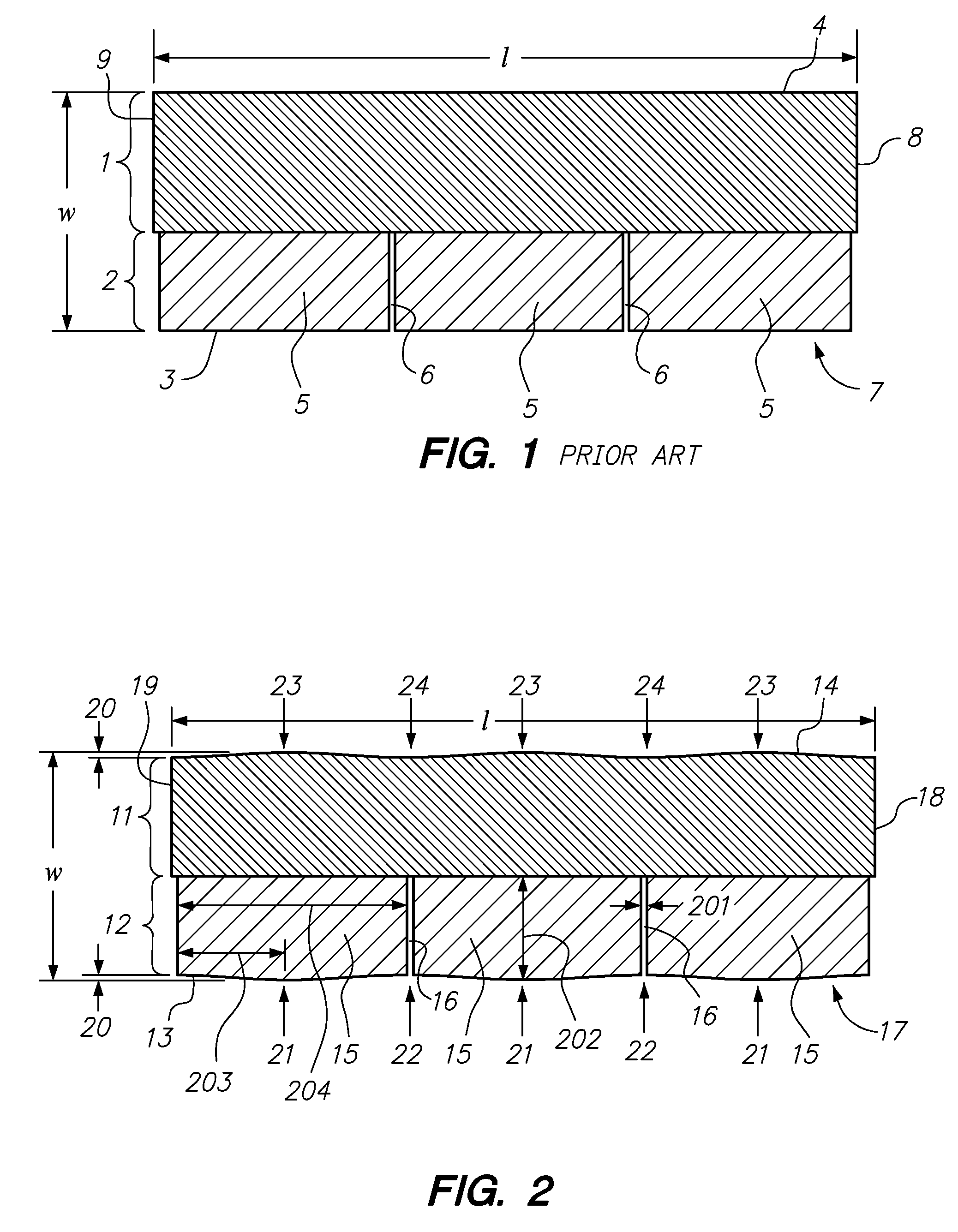
[0037]FIG. 1 represents a typical prior art roofing shingle 7 comprising a headlap portion 1 and a buttlap portion 2. The buttlap portion 2 comprises tabs 5 separated by openings 6. The shingle has a width (w) and a length (l) and comprises generally straight longitudinal edges 3, 4 and generally straight lateral edges 8, 9.

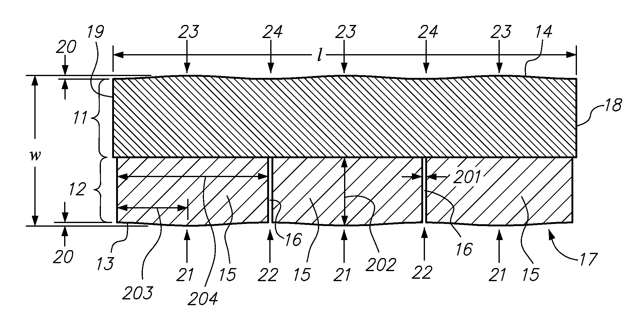
[0038]A shingle 17 incorporating one embodiment of the present invention is shown in FIGS. 2, 4, 6, and 8. Shingle 17 preferably comprises a headlap portion 11 and a buttlap portion 12. The buttlap portion 12 comprises tabs 15 separated by openings 16. The shingles have a maximum width (w) and a length (l) and comprise a non-straight longitudinal headlap edge 14, a non-straight longitudinal buttlap edge 13 and generally straight lateral edges 18, 19. The...


PUM

PropertyMeasurementUnit
widthaaaaaaaaaa
widthaaaaaaaaaa
lengthaaaaaaaaaa

Abstract

A roofing shingle is disclosed comprising a headlap portion with a non-straight longitudinal edge and a buttlap portion with a plurality of tabs with a non-straight longitudinal edge and spaced apart by openings, wherein the non-straight longitudinal edges do not shadow each other laterally across the shingle. A roofing system is disclosed wherein at least a portion of the headlap portion of such shingle from a subsequently installed course overlaps at least a portion of the headlap portion of a shingle from a previously installed course. The maximum headlap overlap dimension is beneath the subsequently installed shingle laterally proximate the openings in the buttlap portion of the subsequently installed shingle. A method for making the shingle is disclosed comprising cutting a sheet of roofing material longitudinally along non-straight lines wherein at least a portion of each formed shingle has a width of about twelve inches.

Description

RELATED APPLICATIONS[0001]This application is a continuation-in-part of design application Ser. No. 29 / 409,522, filed on Dec. 23, 2011, entitled “Shingle;” and a continuation-in-part of design application Ser. No. 29 / 409,523, filed on Dec. 23, 2011, entitled “Shingle;” and a continuation-in-part of design application Ser. No. 29 / 409,524, filed on Dec. 23, 2011, entitled “Shingle;” and a continuation-in-part of design application Ser. No. 29 / 409,527, filed on Dec. 23, 2011, entitled “Shingle;” and a continuation-in-part of design application Ser. No. 29 / 409,532, filed on Dec. 23, 2011, entitled “Shingle;” and a continuation-in-part of design application Ser. No. 29 / 409,533, filed on Dec. 23, 2011, entitled “Shingle.”[0002]The disclosures of all of the aforementioned design applications are incorporated herein by reference.FIELD OF THE INVENTION[0003]This invention relates to an improved roofing shingle and a roofing system that utilizes the shingles. In particular, the invention rela...

Claims


Application Information

Patent Timeline
Patent Type & Authority Patents(United States)
IPC IPC(8): E04D1/26E04D1/22
CPCE04D1/26E04D1/22Y10T83/0524
Inventor LEITCH, OLAN
Owner BMIC LLC
Why Eureka
Try Eureka